

Question: The circuit shown in Fig. Q4 has vin (t) = 5u(t) V as the input voltage and vo(t) as the output voltage. The inductor
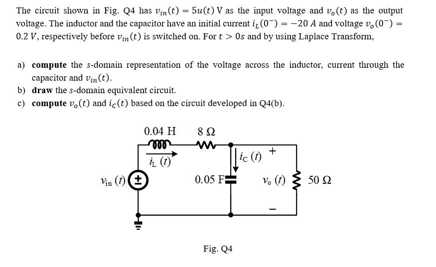
The circuit shown in Fig. Q4 has vin (t) = 5u(t) V as the input voltage and vo(t) as the output voltage. The inductor and the capacitor have an initial current i (0) = -20 A and voltage vo(0) = 0.2 V, respectively before vin (t) is switched on. For t > Os and by using Laplace Transform, a) compute the s-domain representation of the voltage across the inductor, current through the capacitor and Vin (t). b) draw the s-domain equivalent circuit. c) compute vo(t) and ic(t) based on the circuit developed in Q4(b). Vin (1) (+ 0.04 H voo it (t) 8 ww 0.05 F Fig. Q4 ic (t) + vo (t) - 50
Step by Step Solution
3.48 Rating (165 Votes )
There are 3 Steps involved in it
Solutions Step 1 a Using Laplace Transform we can find the sdomain representation of the voltage acr... View full answer

Get step-by-step solutions from verified subject matter experts