

Question: Full information, required to solve homework .. thank you LAB 8 VTC and Large Signal Operation of the CS Circuit 8.1 Objective To study the
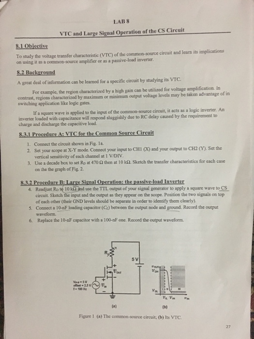
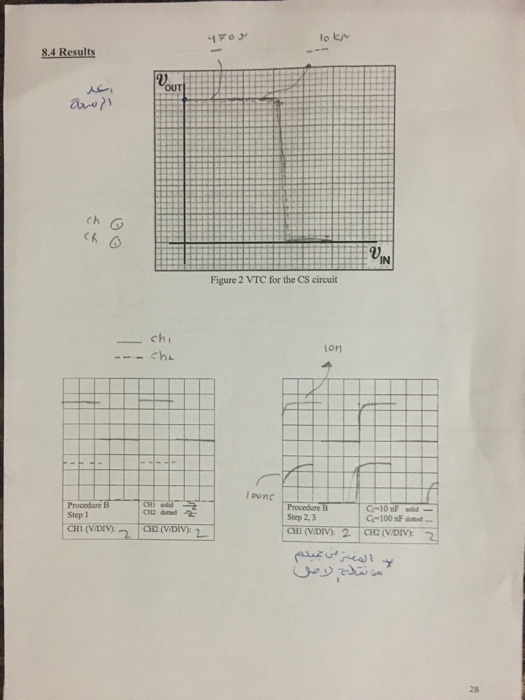
LAB 8 VTC and Large Signal Operation of the CS Circuit 8.1 Objective To study the voltage transfer characteristic (VTC) of the common-source circuit and learn its implications on using it as a common-source amplifier or as a passive-load inverter 8.2 Background A great deal of information can be leamed for a specific circuit by studying its VTC. contrast, regions characterized by maximum or minimum output voltage levels may be taken advantage of in For example, the region characterized by a high gain can be utilized for voltage amplification. In switching application like logic gates If a square wave is applied to the input of the common-source circuit, it acts as a logic inverter. An inverter loaded wi th capacitance will respond sluggishly due to RC delay caused by the requirement to charge and discharge the capacitive load. 8.3.1 Procedure A: VTC for the Common Source Circuit Connect the circuit shown in Fig. 1a. Set your scope at X-Y mode. Connect your input to CHI (X) and your output to CH2 (Y). Set the vertical sensitivity of each channel at 1 V/DIV Use a decade box to set RD at 470 then at 10 kS2. Sketch the transfer characteristics for each case on the the graph of Fig. 2 1. 2. 3, 3.2 Procedure B d Inverter 4. Readjust Ro te 10 kQ ind use the TTL output of your signal generator to apply a square wave to CS 5. Connect a 10-nF loading capacitor (Ct) between the output node and ground. Record the output 6. Replace the 10-nF capacitor with a 100-nF one. Record the output waveform circuit. Sketch the input and the output as they appear on the scope. Position the two signals on top of each other (their GND levels should be separate in order to identify them clearly). waveform. 5 V Vor Figure 1 (a) The common-source circuit, (b) Its VTC. 27
Step by Step Solution
There are 3 Steps involved in it

Get step-by-step solutions from verified subject matter experts