

Question: Q1. a) Refer to Figure Qla, given E = 10 V, R = 1 k2. (i) Draw a circuit diagram to show how an
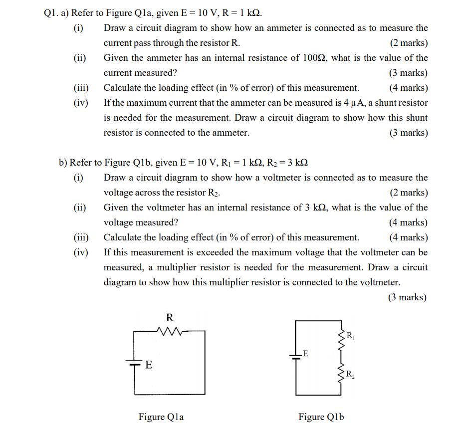
Q1. a) Refer to Figure Qla, given E = 10 V, R = 1 k2. (i) Draw a circuit diagram to show how an ammeter is connected as to measure the current pass through the resistor R. Given the ammeter has an internal resistance of 100Q, what is the value of the (2 marks) (ii) current measured? (3 marks) (iii) Calculate the loading effect (in % of error) of this measurement. (4 marks) (iv) If the maximum current that the ammeter can be measured is 4 A, a shunt resistor is needed for the measurement. Draw a circuit diagram to show how this shunt resistor is connected to the ammeter. (3 marks) b) Refer to Figure Qlb, given E = 10 V, R1 = 1 k, R2 = 3 k2 (i) Draw a circuit diagram to show how a voltmeter is connected as to measure the voltage across the resistor R2. (2 marks) Given the voltmeter has an internal resistance of 3 kN, what is the value of the voltage measured? (ii) (4 marks) (iii) Calculate the loading effect (in % of error) of this measurement. (4 marks) (iv) If this measurement is exceeded the maximum voltage that the voltmeter can be measured, a multiplier resistor is needed for the measurement. Draw a circuit diagram to show how this multiplier resistor is connected to the voltmeter. (3 marks) R R LE E Figure Qla Figure Qlb
Step by Step Solution
3.46 Rating (156 Votes )
There are 3 Steps involved in it

Get step-by-step solutions from verified subject matter experts