

Question: 1 0 . 3 3 The steady - state voltage drop between the load and the sending end of the line seen in Fig. P
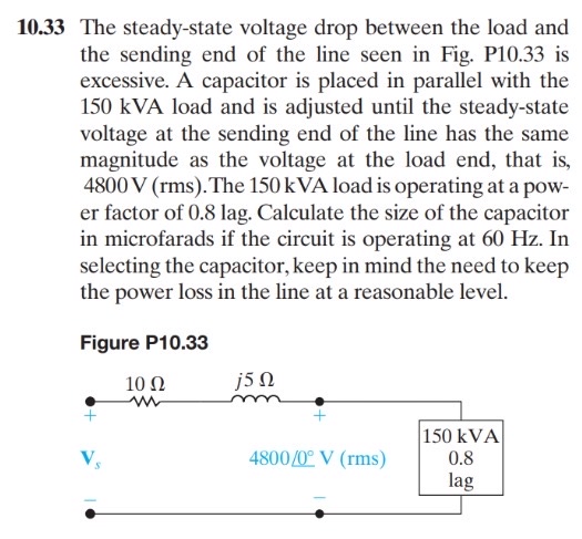
The steadystate voltage drop between the load and the sending end of the line seen in Fig. P is excessive. A capacitor is placed in parallel with the kVA load and is adjusted until the steadystate voltage at the sending end of the line has the same magnitude as the voltage at the load end, that is The kVA load is operating at a power factor of lag. Calculate the size of the capacitor in microfarads if the circuit is operating at Hz In selecting the capacitor, keep in mind the need to keep the power loss in the line at a reasonable level.
Figure P
Step by Step Solution
There are 3 Steps involved in it
1 Expert Approved Answer
Step: 1 Unlock

Question Has Been Solved by an Expert!
Get step-by-step solutions from verified subject matter experts
Step: 2 Unlock
Step: 3 Unlock