

Question: ( 1 0 % ) Analyze the latch circuit shown. ( a ) Derive the next - state equation for this circuit using Q as
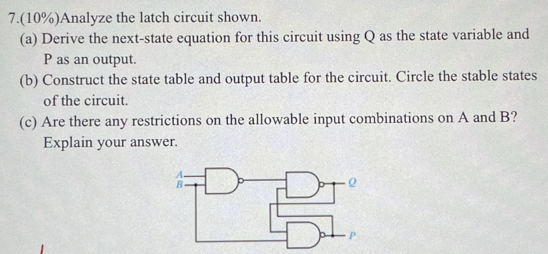
Analyze the latch circuit shown.
a Derive the nextstate equation for this circuit using Q as the state variable and P as an output.
b Construct the state table and output table for the circuit. Circle the stable states of the circuit.
c Are there any restrictions on the allowable input combinations on A and B Explain your answer.
Please answer all three questions
Step by Step Solution
There are 3 Steps involved in it
1 Expert Approved Answer
Step: 1 Unlock

Question Has Been Solved by an Expert!
Get step-by-step solutions from verified subject matter experts
Step: 2 Unlock
Step: 3 Unlock