

Question: QUESTION 1: Design a detector circuit with one input X and one output Y. Whenever the total number of ls received at input X during
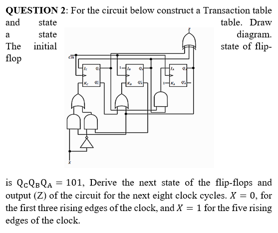
QUESTION 1: Design a detector circuit with one input X and one output Y. Whenever the total number of ls received at input X during the positive edges of the clock signal is odd and greater than 2 means (3, 5, 7, ...), the output Y will be 1, otherwise "0." The "l's at the input X don't need to be successive. A clocked synchronous circuit using Moore model. Example of I/O sequences: X=11100101010 Y=00111001100 a. Draw the state diagram and Fill the State/Output table of the circuit. b. Implement and draw the circuit using positive edge triggered flip- flops and other necessary logic gates. (draw with logisim) QUESTION 2: For the circuit below construct a Transaction table and state table. Draw state diagram The initial state of flip- flop a JC Q LA Q K 02 Qa! R. 04 is QcQB QA = 101, Derive the next state of the flip-flops and output (Z) of the circuit for the next eight clock cycles. X = 0, for the first three rising edges of the clock, and X = 1 for the five rising edges of the clock
Step by Step Solution
There are 3 Steps involved in it

Get step-by-step solutions from verified subject matter experts