

Question: 1 2 . 4 . Consider the liquid - level control system shown in Fig. P 1 2 - 4 . The tanks are noninteract
Consider the liquidlevel control system shown in Fig. P The tanks are noninteract
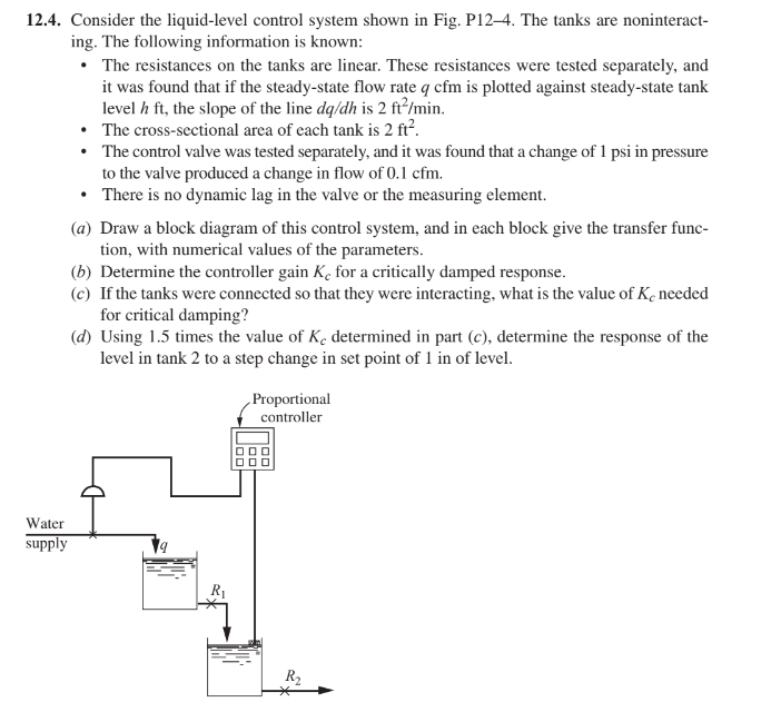
ing. The following information is known:
The resistances on the tanks are linear. These resistances were tested separately, and
it was found that if the steadystate flow rate is plotted against steadystate tank
level the slope of the line is
The crosssectional area of each tank is
The control valve was tested separately, and it was found that a change of in pressure
to the valve produced a change in flow of
There is no dynamic lag in the valve or the measuring element.
a Draw a block diagram of this control system, and in each block give the transfer func
tion, with numerical values of the parameters.
b Determine the controller gain for a critically damped response.
c If the tanks were connected so that they were interacting, what is the value of needed
for critical damping?
d Using times the value of determined in part c determine the response of the
level in tank to a step change in set point of in of level.
Step by Step Solution
There are 3 Steps involved in it
1 Expert Approved Answer
Step: 1 Unlock

Question Has Been Solved by an Expert!
Get step-by-step solutions from verified subject matter experts
Step: 2 Unlock
Step: 3 Unlock