

Question: ( 1 2 Marks ) 3 . ( a ) The circuit in Figure 3 . 1 is designed such that the 5 0 Hz
Marks
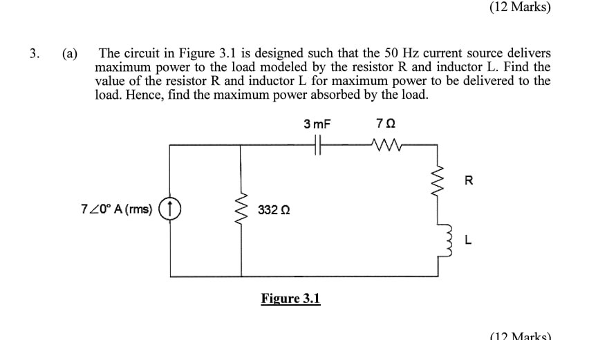
a The circuit in Figure is designed such that the Hz current source delivers maximum power to the load modeled by the resistor R and inductor L Find the value of the resistor R and inductor L for maximum power to be delivered to the load. Hence, find the maximum power absorbed by the load.
Step by Step Solution
There are 3 Steps involved in it
1 Expert Approved Answer
Step: 1 Unlock

Question Has Been Solved by an Expert!
Get step-by-step solutions from verified subject matter experts
Step: 2 Unlock
Step: 3 Unlock