

Question: 1 4 . 2 3 Figure P 1 4 . 2 3 shows a countershaft with helical gear ( B ) , bevel gear (
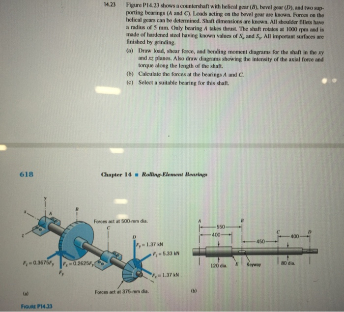
Figure P shows a countershaft with helical gear B bevel gear D and two sup
porting bearings A and Loads acting on the bevel gear are known. Forces on the
helical gears can be determined. Shaft dimensions are known. All shoulder fillets have
a radius of mm Only bearing A takes thrust. The shaft rotates at rpm and is
made of hardened steel having known values of and All important surfaces are
finished by grinding.
a Draw load, shear force, and bending moment diagrams for the shaft in the
and planes. Also draw diagrams showing the intensity of the axial force and
torque along the length of the shaft.
b Calculate the forces at the bearings A and
c Select a suitable bearing for this shaft.
Chapter RollingElement Bearings
a
Forces act at dia.
b
Figuke P
Please specify the book name for this question pleeeaase
Write the book name!
Step by Step Solution
There are 3 Steps involved in it
1 Expert Approved Answer
Step: 1 Unlock

Question Has Been Solved by an Expert!
Get step-by-step solutions from verified subject matter experts
Step: 2 Unlock
Step: 3 Unlock