Question: 1. Consider a hydraulic system with a feedback loop shown in Fig. 1. The hydraulic system has a first pump with prescribed pressure Psi(t) on
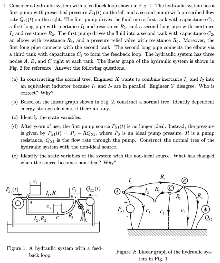
1. Consider a hydraulic system with a feedback loop shown in Fig. 1. The hydraulic system has a first pump with prescribed pressure Psi(t) on the left and a second pump with prescribed flow rate Qs2(t) on the right. The first pump drives the fluid into a first tank with capacitance C1, a first long pipe with inertance I, and resistance Ri, and a second long pipe with inertance 12 and resistance R2. The first pump drives the fluid into a second tank with capacitance C2, an elbow with resistance R3, and a pressure relief valve with resistance R4. Moreover, the first long pipe connects with the second tank. The second long pipe connects the elbow via a third tank with capacitance C3 to form the feedback loop. The hydraulic system has three nodes A, B, and C right at each tank. The linear graph of the hydraulic system is shown in Fig. 2 for reference. Answer the following questions. (a) In constructing the normal tree, Engineer X wants to combine inertance 11 and 12 into an equivalent inductor because I1 and 12 are in parallel. Engineer Y disagree. Who is correct? Why? (b) Based on the linear graph shown in Fig. 2, construct a normal tree. Identify dependent energy storage elements if there are any. (c) Identify the state variables. (d) After years of use, the first pump source Ps(t) is no longer ideal. Instead, the pressure is given by Ps(t) = Po - RQs, where Po is an ideal pump pressure, R is a pump resistance, Qsi is the flow rate through the pump. Construct the normal tree of the hydraulic system with the non-ideal source. (e) Identify the state variables of the system with the non-ideal source. What has changed when the source becomes non-ideal? Why? R Ps,(t) Qs2(t) R 1,R R3 cz.1 12,R2 Ps1 C R Figure 1: A hydraulic system with a feed- back loop Figure 2: Linear graph of the hydraulic sys- tem in Fig. 1 1. Consider a hydraulic system with a feedback loop shown in Fig. 1. The hydraulic system has a first pump with prescribed pressure Psi(t) on the left and a second pump with prescribed flow rate Qs2(t) on the right. The first pump drives the fluid into a first tank with capacitance C1, a first long pipe with inertance I, and resistance Ri, and a second long pipe with inertance 12 and resistance R2. The first pump drives the fluid into a second tank with capacitance C2, an elbow with resistance R3, and a pressure relief valve with resistance R4. Moreover, the first long pipe connects with the second tank. The second long pipe connects the elbow via a third tank with capacitance C3 to form the feedback loop. The hydraulic system has three nodes A, B, and C right at each tank. The linear graph of the hydraulic system is shown in Fig. 2 for reference. Answer the following questions. (a) In constructing the normal tree, Engineer X wants to combine inertance 11 and 12 into an equivalent inductor because I1 and 12 are in parallel. Engineer Y disagree. Who is correct? Why? (b) Based on the linear graph shown in Fig. 2, construct a normal tree. Identify dependent energy storage elements if there are any. (c) Identify the state variables. (d) After years of use, the first pump source Ps(t) is no longer ideal. Instead, the pressure is given by Ps(t) = Po - RQs, where Po is an ideal pump pressure, R is a pump resistance, Qsi is the flow rate through the pump. Construct the normal tree of the hydraulic system with the non-ideal source. (e) Identify the state variables of the system with the non-ideal source. What has changed when the source becomes non-ideal? Why? R Ps,(t) Qs2(t) R 1,R R3 cz.1 12,R2 Ps1 C R Figure 1: A hydraulic system with a feed- back loop Figure 2: Linear graph of the hydraulic sys- tem in Fig. 1


