

Question: 1) Convert the given step-counter equations below the into a step-counter circuit diagram using the Direct control valve (D.C.V) inputs and step-counter inputs. Actuator B
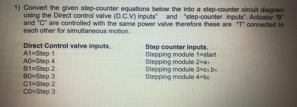
1) Convert the given step-counter equations below the into a step-counter circuit diagram using the Direct control valve (D.C.V) inputs and step-counter inputs". Actuator "B" and "C" are controlled with the same power valve therefore these are "T" connected to each other for simultaneous motion. Direct Control valve inputs, A1=Step 1 AO=Step 4 B1=Step 2 BO=Step 3 C1=Step 2 CO=Step 3 Step counter inputs, Stepping module 1=start Stepping module 2=a1 Stepping module 3=C1.b1 Stepping module 4=bo 1) Convert the given step-counter equations below the into a step-counter circuit diagram using the Direct control valve (D.C.V) inputs and step-counter inputs". Actuator "B" and "C" are controlled with the same power valve therefore these are "T" connected to each other for simultaneous motion. Direct Control valve inputs, A1=Step 1 AO=Step 4 B1=Step 2 BO=Step 3 C1=Step 2 CO=Step 3 Step counter inputs, Stepping module 1=start Stepping module 2=a1 Stepping module 3=C1.b1 Stepping module 4=bo
Step by Step Solution
There are 3 Steps involved in it

Get step-by-step solutions from verified subject matter experts