

Question: 1. Create a full-adder sub-circuit in Logisim from the schematic diagram given in Figure 1. From the main menu: Project>>Add Circuit... Test the circuit and
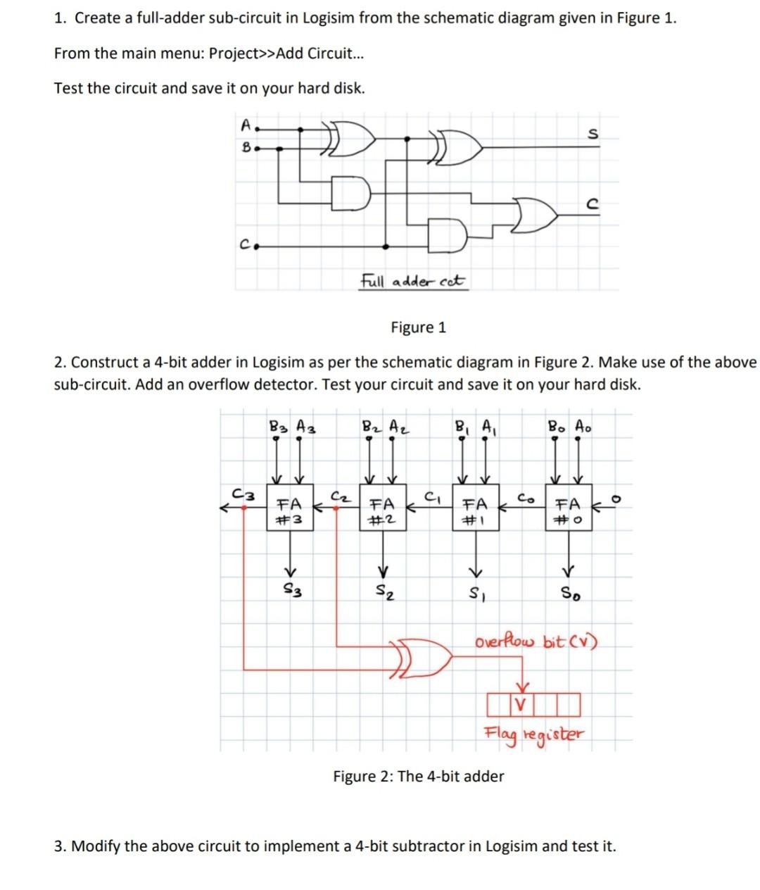
1. Create a full-adder sub-circuit in Logisim from the schematic diagram given in Figure 1. From the main menu: Project>>Add Circuit... Test the circuit and save it on your hard disk. A. B s DO D C. Full adder cat Figure 1 2. Construct a 4-bit adder in Logisim as per the schematic diagram in Figure 2. Make use of the above sub-circuit. Add an overflow detector. Test your circuit and save it on your hard disk. B3 A3 B2 A2 BA B. 4. V C3 . CI FA #3 FA co FA #1 FAKO #2 #O > v S3 S2 is So Overflow bit cv) IV Flag register Figure 2: The 4-bit adder 3. Modify the above circuit to implement a 4-bit subtractor in Logisim and test it
Step by Step Solution
There are 3 Steps involved in it
1 Expert Approved Answer
Step: 1 Unlock

Question Has Been Solved by an Expert!
Get step-by-step solutions from verified subject matter experts
Step: 2 Unlock
Step: 3 Unlock