

Question: For each decimal number given by the binary representation n 3 n 2 n 1 and n 0 ( 4 bits ) , your circuit
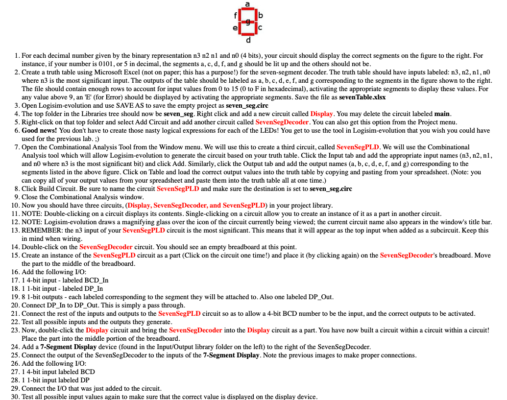
For each decimal number given by the binary representation n n n and n bits your circuit should display the correct segments on the figure to the right. For
instance, if your number is or in decimal, the segments a c d f and g should be lit up and the others should not be
Create a truth table using Microsoft Excel not on paper; this has a purpose! for the sevensegment decoder. The truth table should have inputs labeled: n n n n
where n is the most significant input. The outputs of the table should be labeled as and corresponding to the segments in the figure shown to the right.
The file should contain enough rows to account for input values from to to F in hexadecimal activating the appropriate segments to display these values. For
any value above an for Error should be displayed by activating the appropriate segments. Save the file as sevenTable.xlsx
Open Logisimevolution and use SAVE AS to save the empty project as sevenseg.circ
The top folder in the Libraries tree should now be sevenseg. Right click and add a new circuit called Display. You may delete the circuit labeled main.
Rightclick on that top folder and select Add Circuit and add another circuit called SevenSegDecoder. You can also get this option from the Project menu.
Good news! You don't have to create those nasty logical expressions for each of the LEDs! You get to use the tool in Logisimevolution that you wish you could have
used for the previous lab.
Open the Combinational Analysis Tool from the Window menu. We will use this to create a third circuit, called SevenSegPLD. We will use the Combinational
Analysis tool which will allow Logisimevolution to generate the circuit based on your truth table. Click the Input tab and add the appropriate input names n n n
and n where n is the most significant bit and click Add. Similarly, click the Output tab and add the output names a b c d e f and g corresponding to the
segments listed in the above figure. Click on Table and load the correct output values into the truth table by copying and pasting from your spreadsheet. Note: you
can copy all of your output values from your spreadsheet and paste them into the truth table all at one time.
Click Build Circuit. Be sure to name the circuit SevenSegPLD and make sure the destination is set to sevenseg.circ
Close the Combinational Analysis window.
Now you should have three circuits, Display SevenSegDecoder, and SevenSegPLD in your project library.
NOTE: Doubleclicking on a circuit displays its contents. Singleclicking on a circuit allow you to create an instance of it as a part in another circuit.
NOTE: Logisimevolution draws a magnifying glass over the icon of the circuit currently being viewed; the current circuit name also appears in the window's title bar.
REMEMBER: the n input of your SevenSegPLD circuit is the most significant. This means that it will appear as the top input when added as a subcircuit. Keep this
in mind when wiring.
Doubleclick on the SevenSegDecoder circuit. You should see an empty breadboard at this point.
Create an instance of the SevenSegPLD circuit as a part Click on the circuit one time! and place it by clicking again on the SevenSegDecoder's breadboard. Move
the part to the middle of the breadboard.
Add the following IO:
bit input labeled BCDIn
bit input labeled DPIn
bit outputs each labeled corresponding to the segment they will be attached to Also one labeled DPOut.
Connect DPIn to DPOut. This is simply a pass through.
Connect the rest of the inputs and outputs to the SevenSegPLD circuit so as to allow a bit BCD number to be the input, and the correct outputs to be activated.
Test all possible inputs and the outputs they generate.
Now, doubleclick the Display circuit and bring the SevenSegDecoder into the Display circuit as a part. You have now built a circuit within a circuit within a circuit!
Place the part into the middle portion of the breadboard.
Add a Segment Display device found in the InputOutput library folder on the left to the right of the SevenSegDecoder.
Connect the output of the SevenSegDecoder to the inputs of the Segment Display. Note the previous images to make proper connections.
Add the following IO:
bit input labeled BCD
bit input labeled DP
Connect the IO that was just added to the circuit.
Test all possible input values again to make sure that the correct value is displayed on the display device.
Step by Step Solution
There are 3 Steps involved in it
1 Expert Approved Answer
Step: 1 Unlock

Question Has Been Solved by an Expert!
Get step-by-step solutions from verified subject matter experts
Step: 2 Unlock
Step: 3 Unlock