

Question: 1. Design the control unit that would generate the control signals shown in Table 1. 2. Draw a circuit diagram of the calculator showing the
1. Design the control unit that would generate the control signals shown in Table 1.
2. Draw a circuit diagram of the calculator showing the connections for all the components.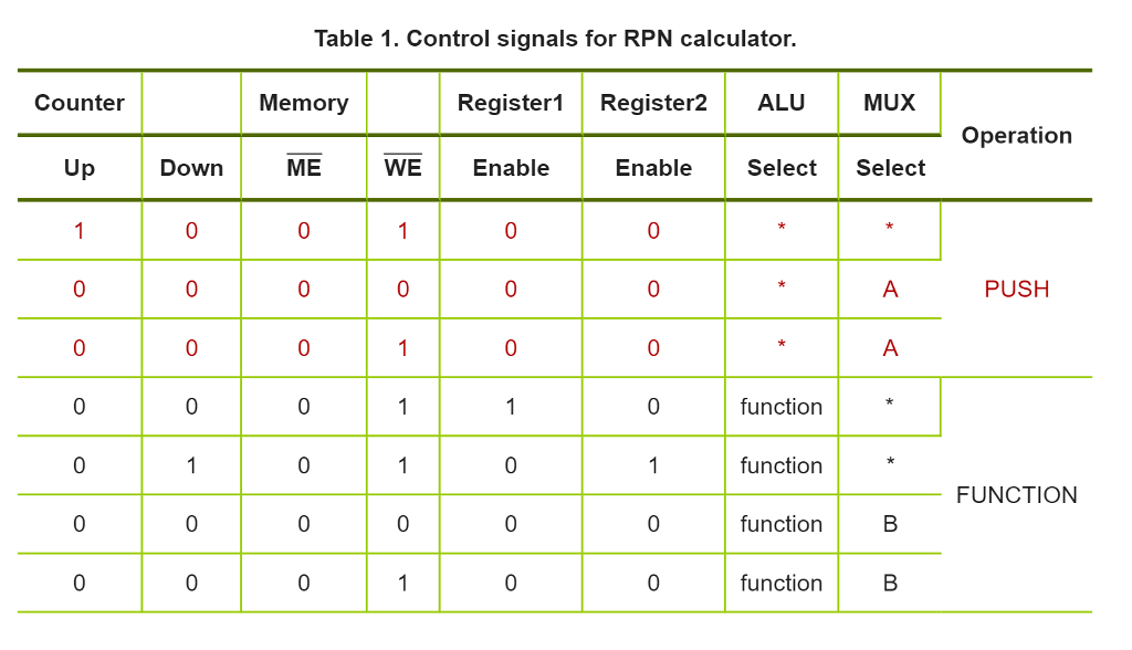
Table 1. Control signals for RPN calculator. Register 1 Register2 ALU Mux Memory Counter Operation Enable Select Select Down ME WE Up Enable 0 0 0 0 PUSH function 0 0 1 function FUNCTION 0 0 0 0 function B 0 0 0 0 function B Table 1. Control signals for RPN calculator. Register 1 Register2 ALU Mux Memory Counter Operation Enable Select Select Down ME WE Up Enable 0 0 0 0 PUSH function 0 0 1 function FUNCTION 0 0 0 0 function B 0 0 0 0 function B
Step by Step Solution
There are 3 Steps involved in it
1 Expert Approved Answer
Step: 1 Unlock

Question Has Been Solved by an Expert!
Get step-by-step solutions from verified subject matter experts
Step: 2 Unlock
Step: 3 Unlock