

Question: The table below shows the controls signal for a reverse polish notation calculator. Please design the control unit based on the control signals in the
The table below shows the controls signal for a reverse polish notation calculator. Please design the control unit based on the control signals in the table and design the circuit diagram.
1) Design the control unit that would generate the control signals shown in Table 1.
2) Draw a circuit diagram of the calculator showing the connections for all the components.
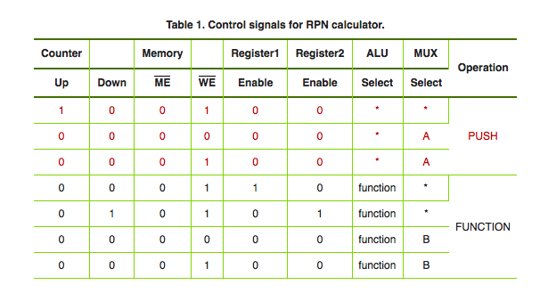
Table 1. Control signals for RPN calculator. Counter Register1 Register2 ALU UX Operation Up Down ME WE Enable Enable Select Select 0 0 0 0 0 0 0 PUSH function' function- functionB functionB FUNCTION Table 1. Control signals for RPN calculator. Counter Register1 Register2 ALU UX Operation Up Down ME WE Enable Enable Select Select 0 0 0 0 0 0 0 PUSH function' function- functionB functionB FUNCTION
Step by Step Solution
There are 3 Steps involved in it

Get step-by-step solutions from verified subject matter experts