

Question: 1. Draw the logic circuit diagram for a 21 multiplexer implemented using NAND gates only. The multiplexer inputs are a and b, and the selection
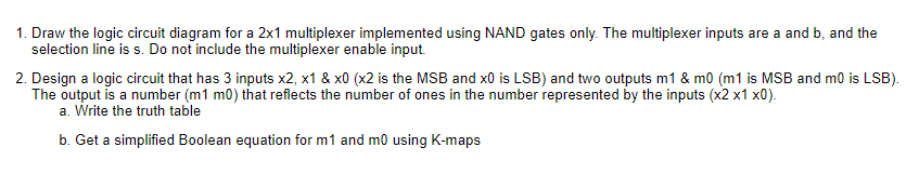
1. Draw the logic circuit diagram for a 21 multiplexer implemented using NAND gates only. The multiplexer inputs are a and b, and the selection line is s. Do not include the multiplexer enable input. 2. Design a logic circuit that has 3 inputs x2,x1&x0 ( x2 is the MSB and x0 is LSB) and two outputs m1&m0(m1 is MSB and m0 is LSB). The output is a number (m1m0) that reflects the number of ones in the number represented by the inputs (210). a. Write the truth table b. Get a simplified Boolean equation for m1 and m0 using K-maps
Step by Step Solution
There are 3 Steps involved in it
1 Expert Approved Answer
Step: 1 Unlock

Question Has Been Solved by an Expert!
Get step-by-step solutions from verified subject matter experts
Step: 2 Unlock
Step: 3 Unlock