

Question: 1 - Implement the circuit given in Figure 5 . 1 by using logic gates EXPERIMENT 5 . 2 RS LATCH BY USING NOR GATES
Implement the circuit given in Figure by using logic gates
EXPERIMENT RS LATCH BY USING NOR GATES
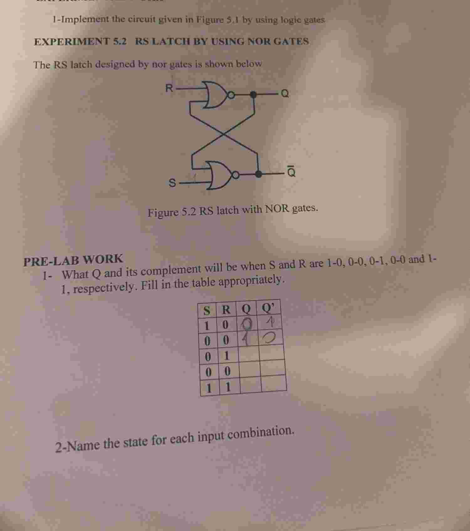
The RS latch designed by nor gates is shown below
Figure RS latch with NOR gates.
PRELAB WORK
What Q and its complement will be when S and R are and respectively. Fill in the table appropriately.
Name the state for each input combination.
Step by Step Solution
There are 3 Steps involved in it
1 Expert Approved Answer
Step: 1 Unlock

Question Has Been Solved by an Expert!
Get step-by-step solutions from verified subject matter experts
Step: 2 Unlock
Step: 3 Unlock