

Question: 1. Pipelining Pipelining is an implementation technique in which multiple instructions are overlapped in execution. The five-stage pipelined CPU allows overlapping execution of multiple instructions.
1. Pipelining
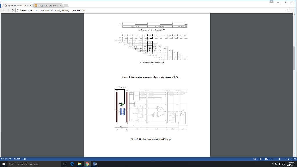
Pipelining is an implementation technique in which multiple instructions are overlapped in execution. The five-stage pipelined CPU allows overlapping execution of multiple instructions. Although an instruction takes fiveclock cycle to pass through the pipeline, a new instruction can enter the pipeline during every clock cycle. Underideal circumstances, the pipelined CPU can produce a result in every clock cycle. Because in a pipelined CPUthere are multiple operations in each clock cycle, we must save the temporary results in each pipeline stage intopipeline registers for use in the follow-up stages. We have five stages: IF, ID, EXE, MEM, and WB. The PC canbe considered as the first pipeline register at the beginning of the first stage. We name the other pipeline registersas IF/ID, ID/EXE, EXE/MEM, and MEM/WB in sequence. In order to understand in depth how the pipelinedCPU works, we will show the circuits that are required in each pipeline stage of a baseline CPU.
2. Circuits of the Instruction Fetch Stage
The circuit in the IF stage are shown in Figure 2. Also, looking at the first clock cycle in Figure 1(b), the first lwinstruction is being fetched. In the IF stage, there is an instruction memory module and an adder between twopipeline registers. The left most pipeline register is the PC; it holds 100. In the end of the first cycle (at the risingedge of clk), the instruction fetched from instruction memory is written into the IF/ID register. Meanwhile, theoutput of the adder (PC + 4, the next PC) is written into PC.
3. Circuits of the Instruction Decode Stage
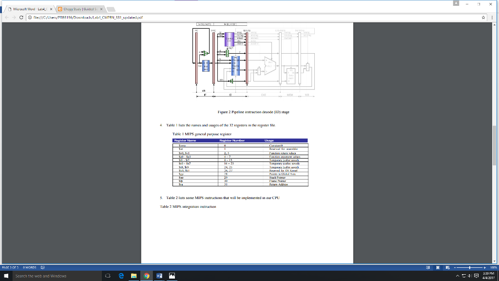
Referring to Figure 3, in the second cycle, the first instruction entered the ID stage. There are two jobs in thesecond cycle: to decode the first instruction in the ID stage, and to fetch the second instruction in the IF stage. Thetwo instructions are shown on the top of the figures: the first instruction is in the ID stage, and the secondinstruction is in the IF stage. The first instruction in the ID stage comes from the IF/ID register. Two operands areread from the register file (Regfile in the figure) based on rs and rt, although the lw instruction does not use theoperand in the register rt. The immediate (imm) is sign- extended into 32 bits. The regrt signal is used in the IDstage that selects the destination register number; all others must be written into the ID/EXE register for later use.At the end of the second cycle, all the data and control signals, except for regrt, in the ID stage are written into theID/EXE register. At the same time, the PC and the IF/ID register are also updated.
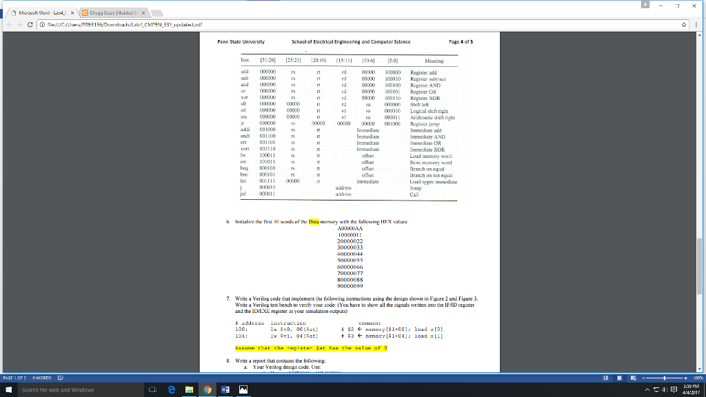
6. Initialize the first 10 words of the Data memory with the following
HEX values:
A00000AA
10000011
20000022
30000033
40000044
50000055
60000066
70000077
80000088
90000099
7. Write a Verilog code that implement the following instructions using the design shown in Figure 2 and Figure 3. Write a Verilog test bench to verify your code: (You have to show all the signals written into the IF/ID register and the ID/EXE register in your simulation outputs)
# address instruction comment
100: lw $v0, 00($at) # $2
104: lw $v1, 04($at) # $3
Assume that the register $at has the value of 0.
he Web and Mindows update pdl fH Timing Figure ng chart parison between two types CPUs igure 2 Pipeline instructi fetch (IF stage he Web and Mindows update pdl fH Timing Figure ng chart parison between two types CPUs igure 2 Pipeline instructi fetch (IF stage
Step by Step Solution
There are 3 Steps involved in it

Get step-by-step solutions from verified subject matter experts