

Question: 1. The rectangular plate shown in (a) is modelled by Student A using the 3-noded triangular element as shown in (b). The node labels
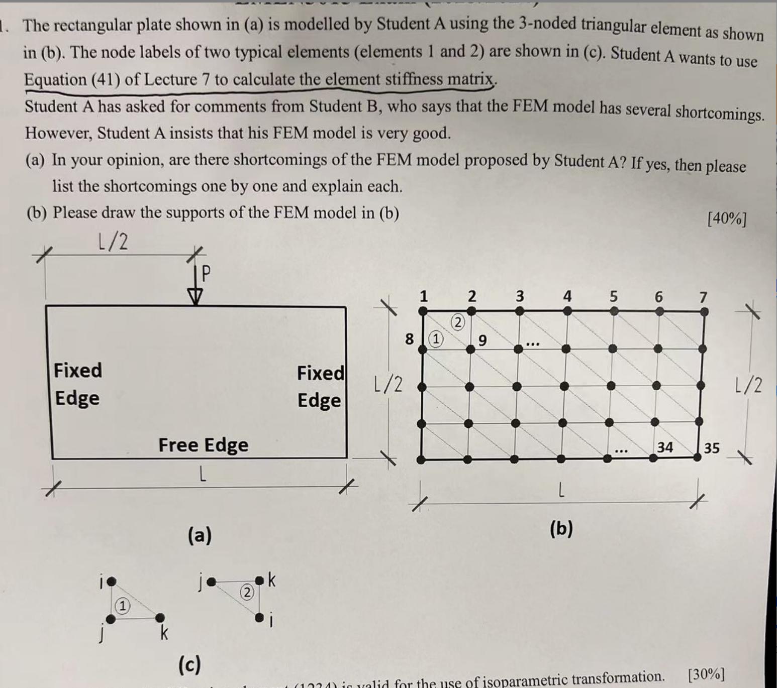
1. The rectangular plate shown in (a) is modelled by Student A using the 3-noded triangular element as shown in (b). The node labels of two typical elements (elements 1 and 2) are shown in (c). Student A wants to use Equation (41) of Lecture 7 to calculate the element stiffness matrix. Student A has asked for comments from Student B, who says that the FEM model has several shortcomings. However, Student A insists that his FEM model is very good. (a) In your opinion, are there shortcomings of the FEM model proposed by Student A? If yes, then please list the shortcomings one by one and explain each. (b) Please draw the supports of the FEM model in (b) [40%] 2 3 4 5 6 7 1/2 |P V 1 (2) 8 1 9 Fixed Fixed L/2 Edge Edge Free Edge L 1 k (a) 1 (c) 2 k L (b) 34 35 1024) is valid for the use of isoparametric transformation. L/2 [30%]
Step by Step Solution
There are 3 Steps involved in it
a Yes there are shortcomings in the FEM model proposed by Student A Here are the shortcomings 1 Element Type Student A is using a 3noded triangular el... View full answer

Get step-by-step solutions from verified subject matter experts