

Question: (15 points) Realize the finite state machine using at most eight two-input NAND gates, six three-input NAND gates, four four-input NAND gates, one eight-input NAND
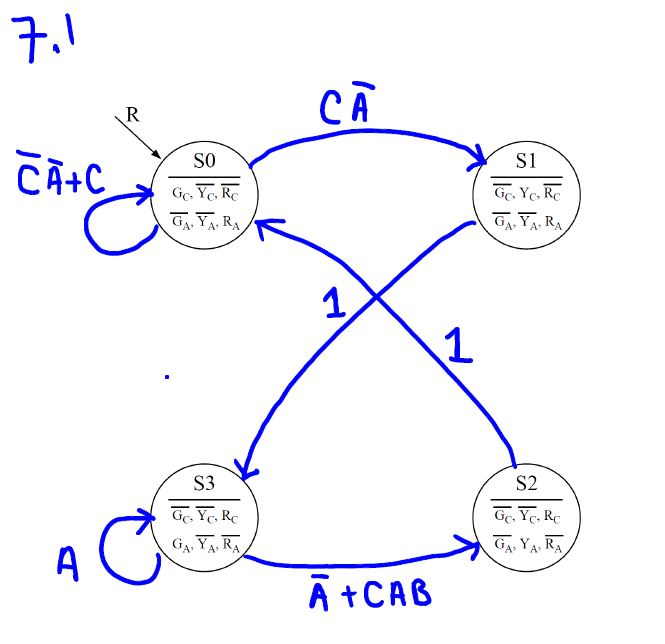
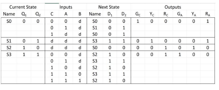
(15 points) Realize the finite state machine using at most eight two-input NAND gates, six three-input NAND gates, four four-input NAND gates, one eight-input NAND gate, and two D-type flip-flops. Assume that each D-type flip-flop has an asynchronous input labeled CLR that drives the flip-flop output to logic low whenever the value of CLR is logic high; these will serve as your reset input. If it is necessary to invert a logic level, wire one of the NAND gates as an inverter. Neatly sketch your circuit. As an alternative to sketching, you can use Lab 3, Exercise 2 as an example to implement the logic diagram in Multisim; specifically, see the circuit implemented on page 19. You are just "sketching" at this point so no need for the function generator to represent the clock. As part of your first project you will use Multisim to simulate your FSM, so you will be able to use your Multisim sketch as the basis for your simulation. (15 points) Realize the finite state machine using at most eight two-input NAND gates, six three-input NAND gates, four four-input NAND gates, one eight-input NAND gate, and two D-type flip-flops. Assume that each D-type flip-flop has an asynchronous input labeled CLR that drives the flip-flop output to logic low whenever the value of CLR is logic high; these will serve as your reset input. If it is necessary to invert a logic level, wire one of the NAND gates as an inverter. Neatly sketch your circuit. As an alternative to sketching, you can use Lab 3, Exercise 2 as an example to implement the logic diagram in Multisim; specifically, see the circuit implemented on page 19. You are just "sketching" at this point so no need for the function generator to represent the clock. As part of your first project you will use Multisim to simulate your FSM, so you will be able to use your Multisim sketch as the basis for your simulation
Step by Step Solution
There are 3 Steps involved in it

Get step-by-step solutions from verified subject matter experts