

Question: 2 . ( 1 5 points ) 3 . 3 V Use the circuit above to complete the program which starts below, and ends at
points
V
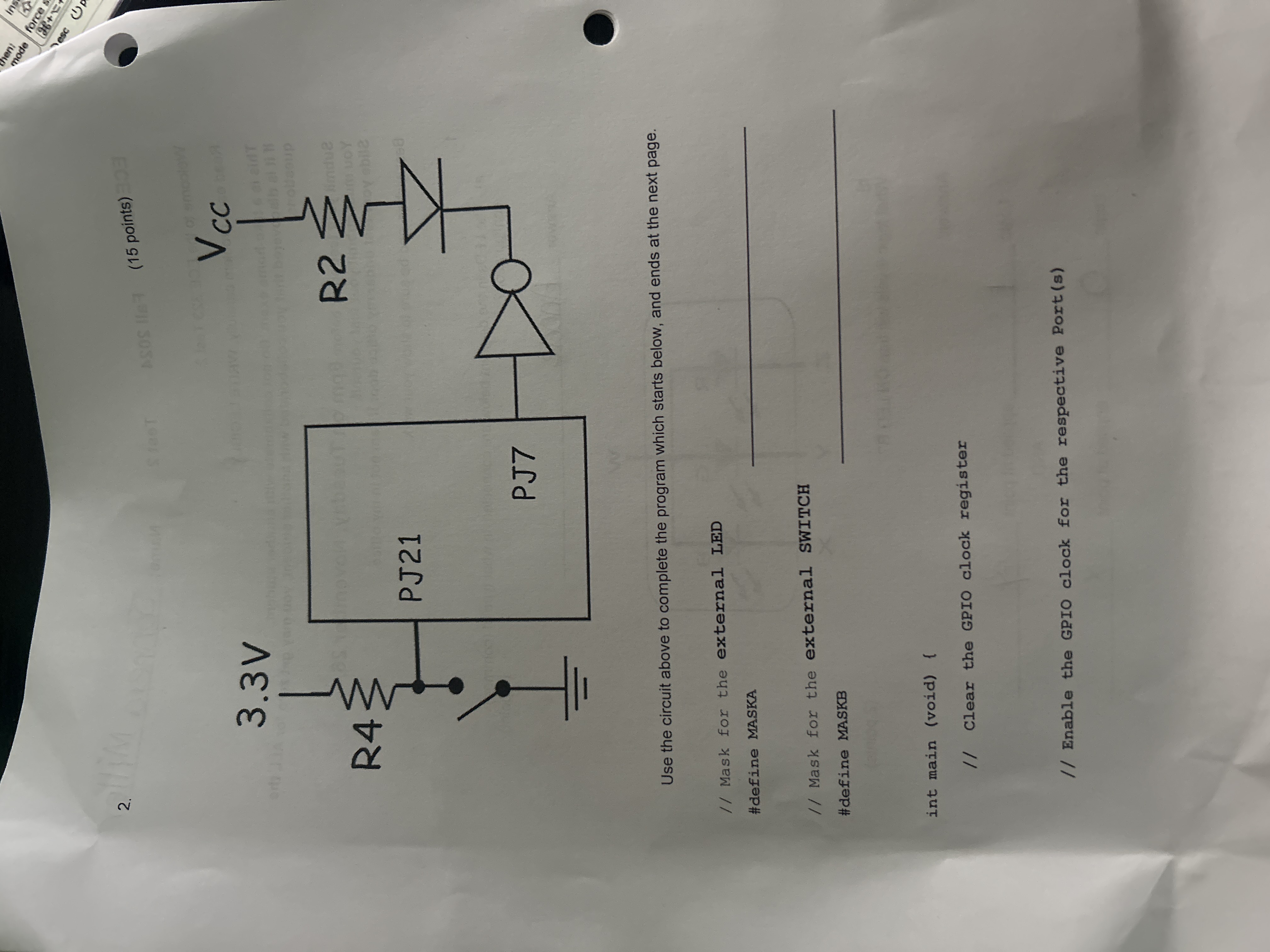
Use the circuit above to complete the program which starts below, and ends at the next page.
Mask for the external LED
#define MASKA
Mask for the external SWITCH
#define MASKB
int main void
Clear the GPIO clock register
Enable the GRIO clock for the respective Ports
Enable digital function at the GPIO ports for the
external switch and external LED
Set the direction input or output of the GPIO pin connected to
the inverter
Set the direction of the GPIO pin connected to the
external switch
Turn off the external LED
If the external switch is closed,
toggle the external LED;
Step by Step Solution
There are 3 Steps involved in it
1 Expert Approved Answer
Step: 1 Unlock

Question Has Been Solved by an Expert!
Get step-by-step solutions from verified subject matter experts
Step: 2 Unlock
Step: 3 Unlock