

Question: 2. 4-Bit Magnitude Comparator Use PSPICE to implement a 4-bit magnitude comparator circuit using a 7485. Add 4 clocks to the schematic defined as follows:
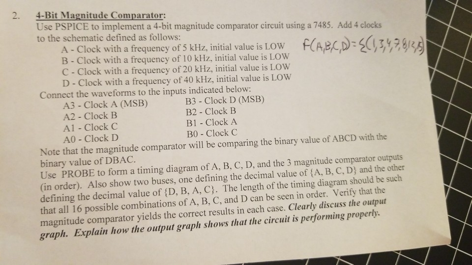
2. 4-Bit Magnitude Comparator Use PSPICE to implement a 4-bit magnitude comparator circuit using a 7485. Add 4 clocks to the schematic defined as follows: A-Clock with a frequency of 5 kHz initial value is Low B - Clock with a frequency of 10 kHz, initial value is LOW C - Clock with a frequency of 20 kHz, initial value is LOW D - Clock with a frequency of 40 kHz, initial value is LOW RA (D:5( Connect the waveforms to the inputs indicated below: A3-Clock A (MSB) A2 Clock B A1 - Clock C A0 - Clock D B3 - Clock D (MSB) B2 - Clock B B1 - Clock A B0 Clock C Note that the magnitude comparator will be comparing the binary value of ABCD with the binary value of DBAC. Use PROBE to form a timing diagram of A, B, C, D, and the 3 magnitude comparator outputs (in order). Also show two buses, one defining the decimal value of (A, B, C, D) and the other defining the decimal value of (D, B, A, C). The length of the timing diagram should be such that all 16 possible combinations of A, B, C, and D can be seen in order. Verify that the magnitude comparator yields the correct results in each case. Clearly discuss the output graph. Explain how the output graplh shows that the circuit is performing properly. 2. 4-Bit Magnitude Comparator Use PSPICE to implement a 4-bit magnitude comparator circuit using a 7485. Add 4 clocks to the schematic defined as follows: A-Clock with a frequency of 5 kHz initial value is Low B - Clock with a frequency of 10 kHz, initial value is LOW C - Clock with a frequency of 20 kHz, initial value is LOW D - Clock with a frequency of 40 kHz, initial value is LOW RA (D:5( Connect the waveforms to the inputs indicated below: A3-Clock A (MSB) A2 Clock B A1 - Clock C A0 - Clock D B3 - Clock D (MSB) B2 - Clock B B1 - Clock A B0 Clock C Note that the magnitude comparator will be comparing the binary value of ABCD with the binary value of DBAC. Use PROBE to form a timing diagram of A, B, C, D, and the 3 magnitude comparator outputs (in order). Also show two buses, one defining the decimal value of (A, B, C, D) and the other defining the decimal value of (D, B, A, C). The length of the timing diagram should be such that all 16 possible combinations of A, B, C, and D can be seen in order. Verify that the magnitude comparator yields the correct results in each case. Clearly discuss the output graph. Explain how the output graplh shows that the circuit is performing properly
Step by Step Solution
There are 3 Steps involved in it

Get step-by-step solutions from verified subject matter experts