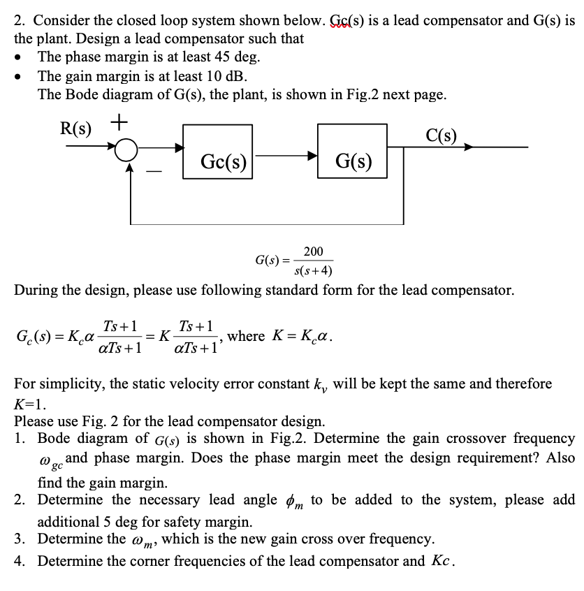
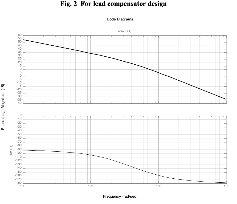
Question: 2. Consider the closed loop system shown below. Go(s) is a lead compensator and (s) is the plant. Design a lead compensator such that The

2. Consider the closed loop system shown below.

2. Consider the closed loop system shown below.

2. Consider the closed loop system shown below. Go(s) is a lead compensator and (s) is the plant. Design a lead compensator such that The phase margin is at least 45 deg. The gain margin is at least 10 dB. The Bode diagram of G(s), the plant, is shown in Fig.2 next page. LC(s) G(s) Ge(s) G(8) = 200 s(s+4) During the design, please use following standard form for the lead compensator. Ts+1 Ge(s) = K a ats +1 = K- Ts +1. where K= K a. als +1 For simplicity, the static velocity error constant k, will be kept the same and therefore K=1. Please use Fig. 2 for the lead compensator design. 1. Bode diagram of G(s) is shown in Fig.2. Determine the gain crossover frequency 0 and phase margin. Does the phase margin meet the design requirement? Also find the gain margin. 2. Determine the necessary lead angle om to be added to the system, please add additional 5 deg for safety margin. 3. Determine the om, which is the new gain cross over frequency. 4. Determine the corner frequencies of the lead compensator and Kc. Fig. 2 For lead compensator design Bode Diagrams From: U(1) Phase (deg); Magnitude (dB) To: Y(1) - 160 -170 -180 10-1 10 Frequency (rad/sec)

Step by Step Solution

There are 3 Steps involved in it

1 Expert Approved Answer
Step: 1 Unlock blur-text-image
Question Has Been Solved by an Expert!

Get step-by-step solutions from verified subject matter experts

Step: 2 Unlock
Step: 3 Unlock

Students Have Also Explored These Related General Management Questions!