

Question: 2. Design a binary to seven-segment code converter system shown in the following figure. Assume logic-0 turn on the LED and logic-1 turns it off.
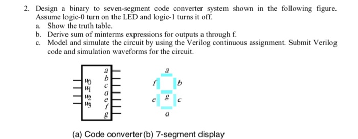
2. Design a binary to seven-segment code converter system shown in the following figure. Assume logic-0 turn on the LED and logic-1 turns it off. a. Show the truth table. b. Derive sum of minterms expressions for outputs a through f. c. Model and simulate the circuit by using the Verilog continuous assignment. Submit Verilog code and simulation waveforms for the circuit. lth (a) Code converter (b) 7-segment display
Step by Step Solution
There are 3 Steps involved in it
1 Expert Approved Answer
Step: 1 Unlock

Question Has Been Solved by an Expert!
Get step-by-step solutions from verified subject matter experts
Step: 2 Unlock
Step: 3 Unlock