

Question: 2. Design an adder/subtractor circuit using 7483 and 7486 chips. A control input, M, determines whether the circuit adds or subtracts two four-bit numbers
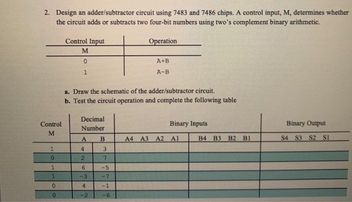
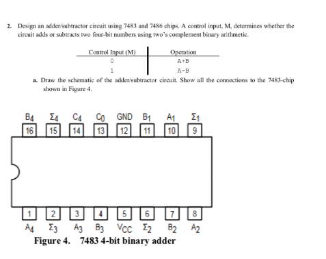
2. Design an adder/subtractor circuit using 7483 and 7486 chips. A control input, M, determines whether the circuit adds or subtracts two four-bit numbers using two's complement binary arithmetic. Control Input M 0 1 Operation A+B A-B a. Draw the schematic of the adder/subtractor circuit. b. Test the circuit operation and complete the following table Decimal Control Binary Inputs Binary Output Number M A B A4 A3 A2 A1 B4 B3 B2 B1 S4 S3 S2 S1 1 4 3 0 2200 1 1 -3 26342 7 -5 -7 -1 -2 -6 2. Design an adder/subtractor circuit using 7483 and 7486 chips. A control input, M, determines whether the circuit adds or subtracts two four-bit numbers using two's complement binary arithmetic. Control Input (M) 0 1 Operation A+B A-B a. Draw the schematic of the adder/subtractor circuit. Show all the connections to the 7483-chip shown in Figure 4. B4 4 C4 Co GND B B1 A1 A1 1 16 15 14 13 12 11 10 9 1234 5 6 7 8 B2 A2 A4 3 A3 B3 VCC 2 B2 Figure 4. 7483 4-bit binary adder
Step by Step Solution
There are 3 Steps involved in it

Get step-by-step solutions from verified subject matter experts