

Question: 2) Draw the initially reset output waveforms for the Flip Flop circuit shown below: DO-0 Di- 1 D2-1 D3-1 Parallel data nputs p2 CLR CLK
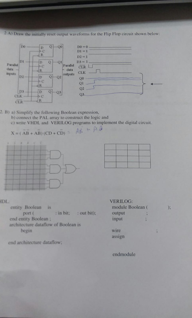
2) Draw the initially reset output waveforms for the Flip Flop circuit shown below: DO-0 Di- 1 D2-1 D3-1 Parallel data nputs p2 CLR CLK data Q1 02 Q3 Da CLK 2 B) a) Simplify the following Boolean expression, b) connect the PAL array to construct the logic and c)write VHDL and VERILOG programs to implement the digital circuit. X (AB+AB) (CD + CD): AD EDD IDL VERILOG entity Boolean i port ( end entity Boolean module Boolean ( output input : in bit, out bit): architecture dataflow of Boolean is begin wire assign end architecture dataflow; endmodule
Step by Step Solution
There are 3 Steps involved in it
1 Expert Approved Answer
Step: 1 Unlock

Question Has Been Solved by an Expert!
Get step-by-step solutions from verified subject matter experts
Step: 2 Unlock
Step: 3 Unlock