

Question: 2. For the element shown in Fig, 1, calculate the element stiffness matrix. The coordinates are in mm. Take E = 70 GPa, v
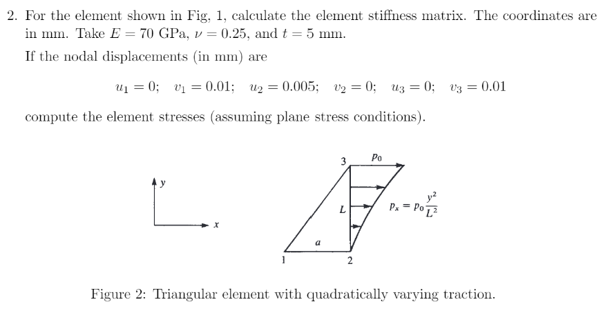
2. For the element shown in Fig, 1, calculate the element stiffness matrix. The coordinates are in mm. Take E = 70 GPa, v = 0.25, and t = 5 mm. If the nodal displacements (in mm) are U = = 0; v = 0.01; u2=0.005; v = 0; uz = 0; v3 = 0.01 compute the element stresses (assuming plane stress conditions). 1 a L 2 Po P = Po[ Figure 2: Triangular element with quadratically varying traction.
Step by Step Solution
There are 3 Steps involved in it
1 Expert Approved Answer
Step: 1 Unlock

Question Has Been Solved by an Expert!
Get step-by-step solutions from verified subject matter experts
Step: 2 Unlock
Step: 3 Unlock