

Question: 3 . 1 6 In Example 3 . 1 5 , it was demonstrated that refrigeration cycles utilizing a heat input to accomplish refrigeration tend
In Example it was demonstrated that refrigeration cycles utilizing a heat input to accomplish refrigeration tend to have a low but a higher exergetic efficiency compared to vapor compression refrigeration cycles using electricity to run a compressor. Consider the combined cycle shown in Figure P that utilizes a heat input to accomplish refrigeration.
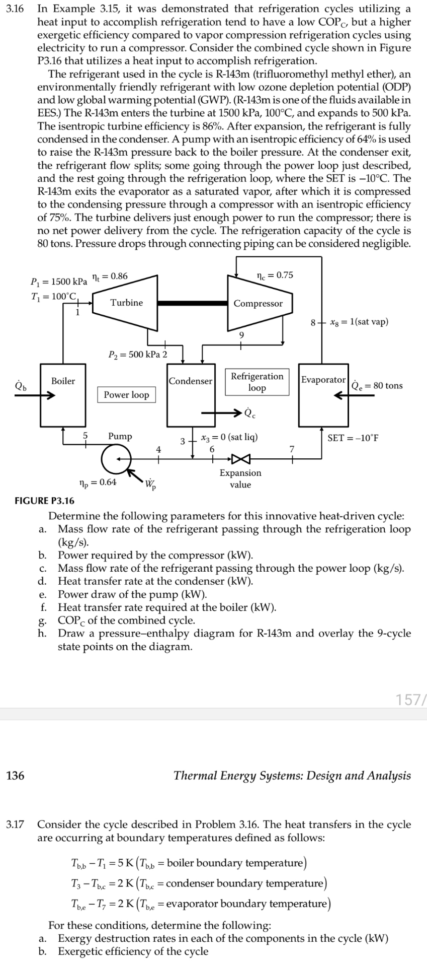
The refrigerant used in the cycle is Rm trifluoromethyl methyl ether an environmentally friendly refrigerant with low ozone depletion potential ODP and low global warming potential GWPRm is one of the fluids available in EES. The Rm enters the turbine at kPa, and expands to kPa The isentropic turbine efficiency is After expansion, the refrigerant is fully condensed in the condenser. A pump with an isentropic efficiency of is used to raise the Rm pressure back to the boiler pressure. At the condenser exit, the refrigerant flow splits; some going through the power loop just described, and the rest going through the refrigeration loop, where the SET is The exits the evaporator as a saturated vapor, after which it is compressed to the condensing pressure through a compressor with an isentropic efficiency of The turbine delivers just enough power to run the compressor; there is no net power delivery from the cycle. The refrigeration capacity of the cycle is tons. Pressure drops through connecting piping can be considered negligible.
Determine the following parameters for this innovative heatdriven cycle:
a Mass flow rate of the refrigerant passing through the refrigeration loop
b Power required by the compressor
c Mass flow rate of the refrigerant passing through the power loop
d Heat transfer rate at the condenser
e Power draw of the pump
f Heat transfer rate required at the boiler
g of the combined cycle.
h Draw a pressureenthalpy diagram for Rm and overlay the cycle state points on the diagram.
Thermal Energy Systems: Design and Analysis
Consider the cycle described in Problem The heat transfers in the cycle are occurring at boundary temperatures defined as follows:
boiler boundary temperature condenser boundary temperature evaporator boundary temperature
For these conditions, determine the following:
a Exergy destruction rates in each of the components in the cycle kW
b Exergetic efficiency of the cycle
Step by Step Solution
There are 3 Steps involved in it
1 Expert Approved Answer
Step: 1 Unlock

Question Has Been Solved by an Expert!
Get step-by-step solutions from verified subject matter experts
Step: 2 Unlock
Step: 3 Unlock