

Question: 3 . 2 The continuous beam shown in Fig. 1 is part of a beam - and - slab floor system of an office building
The continuous beam shown in Fig. is part of a beamandslab floor system of an
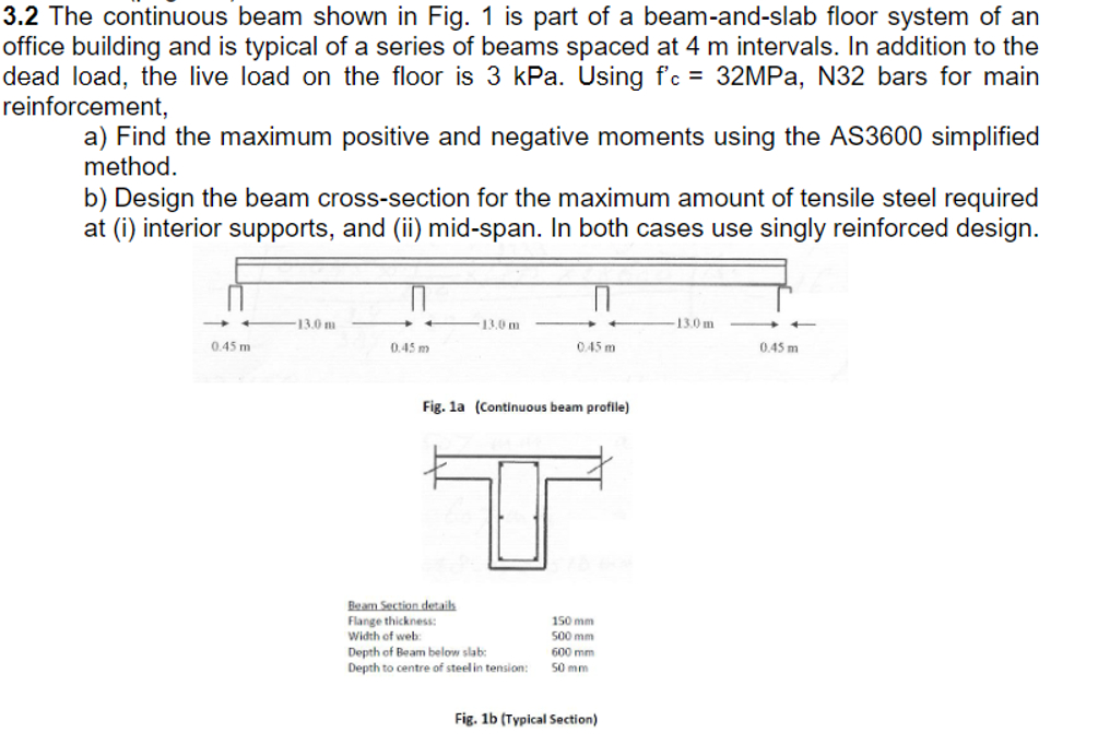
office building and is typical of a series of beams spaced at m intervals. In addition to the
dead load, the live load on the floor is kPa Using MPa, bars for main
reinforcement,
a Find the maximum positive and negative moments using the AS simplified
method.
b Design the beam crosssection for the maximum amount of tensile steel required
at i interior supports, and ii midspan. In both cases use singly reinforced design.
Fig. a Continuous beam profile
Fig. b Typical Section
Step by Step Solution
There are 3 Steps involved in it
1 Expert Approved Answer
Step: 1 Unlock

Question Has Been Solved by an Expert!
Get step-by-step solutions from verified subject matter experts
Step: 2 Unlock
Step: 3 Unlock