

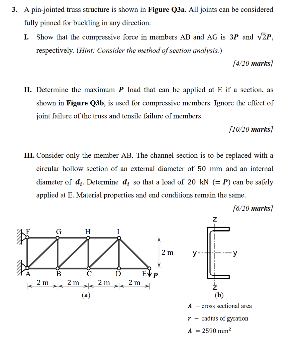
Question: 3 . A pin - jointed truss structure is shown in Figure Q 3 a . All joints can be considered fully pinned for buckling
A pinjointed truss structure is shown in Figure Qa All joints can be considered fully pinned for buckling in any direction.
I. Show that the compressive force in members AB and AG is boldsymbolP and sqrtboldsymbolP respectively. Hint: Consider the method of section analysis.
marks
II Determine the maximum boldsymbolP load that can be applied at E if a section, as shown in Figure Qb is used for compressive members. Ignore the effect of joint failure of the truss and tensile failure of members.
marks
III. Consider only the member AB The channel section is to be replaced with a circular hollow section of an external diameter of mm and an internal diameter of boldsymboldboldsymboli Determine boldsymboldboldsymboli so that a load of mathrmkNboldsymbolP can be safely applied at E Material properties and end conditions remain the same.
marks
A viuss seculial alea
r radius of gyration
boldsymbolAmathrm~mm
Step by Step Solution
There are 3 Steps involved in it
1 Expert Approved Answer
Step: 1 Unlock

Question Has Been Solved by an Expert!
Get step-by-step solutions from verified subject matter experts
Step: 2 Unlock
Step: 3 Unlock