

Question: 3 . VERTICAL ALIGNMENT ( 2 3 MARKS ) Using the information shown on your contour map, draw a longsection of the Centre Line of
VERTICAL ALIGNMENT MARKS
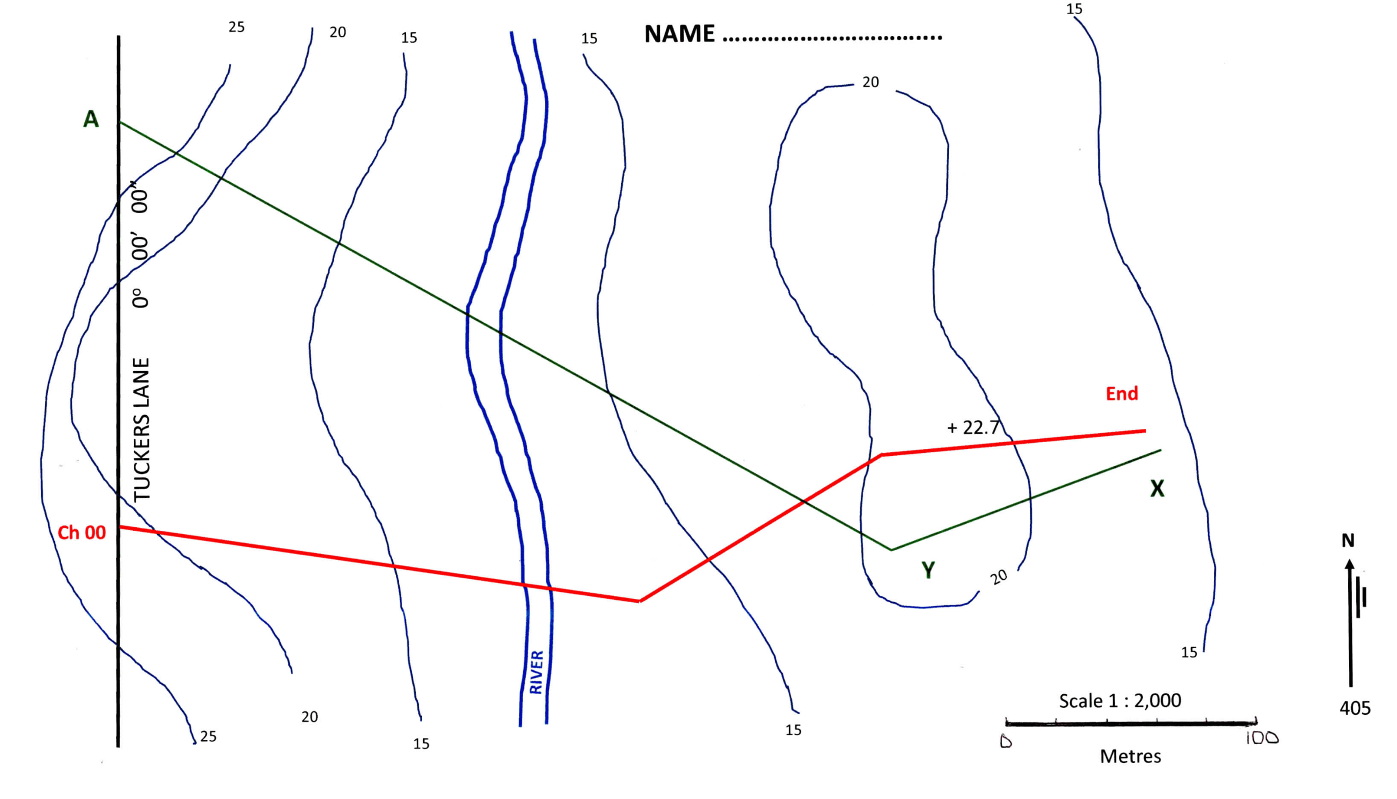
Using the information shown on your contour map, draw a longsection of the Centre Line of your road at scales; horizontal : and vertical :
Scale the distances along the road to each contour and show the results on the table of your answer sheet. Marks
Design a vertical alignment of the centre line of the road showing grades and vertical
curves. The vertical alignment must meet the following criteria:
The road must start at RL It must finish exactly at RL at the chainage you have calculated as being the end of the road.
The Natural Surface RLs at the start and end of the road are exactly the same as the starting and finishing Design RLs of the road at each point.
The first IP of the vertical design must lie at Chainage and RL After that you must complete the vertical design using two or three at most rising grades and one falling grade, which generally follow the land surface. You must aim to keep the road ie the cut or fill within m of the natural surface. If this cannot be achieved in a maximum of four new grades, complete your design using four grades and then make a brief report and explain where the road has excess cut or fill and by how much.
The grades you select for your design of the road must be between and
Vertical curves must have lengths of only mm or m The I.P of each vertical curve must be located at an even m chainage ie etc. and must not be placed at odd locations such as All grades used must be to no greater precision than except for the final grade to the end of the line. ie grades such as must be used for every grade, except the final one where additional decimal places may be shown, if necessary, to ensure that the Design RL meets the set RL
Every change of grade requires a vertical curve. Assume that your road will meet Tuckers Road precisely at the nominated RL No vertical curve will be needed at this road junction.
Complete the table with your vertical curve calculations for the design levels.
Calculate the Design Levels at every m of running chainage along the road. Also calculate the chainage to dp and RL of the low point of the road at the river crossing.
a In the drawing section, the natural surface, grade lines and the road design. You must also note the extent of each grade and the regions where the vertical curves are located. Also show each IPRL and Mid Ordinate value.
b in the data rows, the distances and natural surface RLs used to plot the natural surface;
the distances and Design RLs at the chainage of each IP of the vertical alignment only.
Step by Step Solution
There are 3 Steps involved in it
1 Expert Approved Answer
Step: 1 Unlock

Question Has Been Solved by an Expert!
Get step-by-step solutions from verified subject matter experts
Step: 2 Unlock
Step: 3 Unlock