

Question: 3A. For the circuit shown below, complete the truth table. 5 RO !S !R Qcurr Qnew 0 0 0 0 0 1 0 1 0
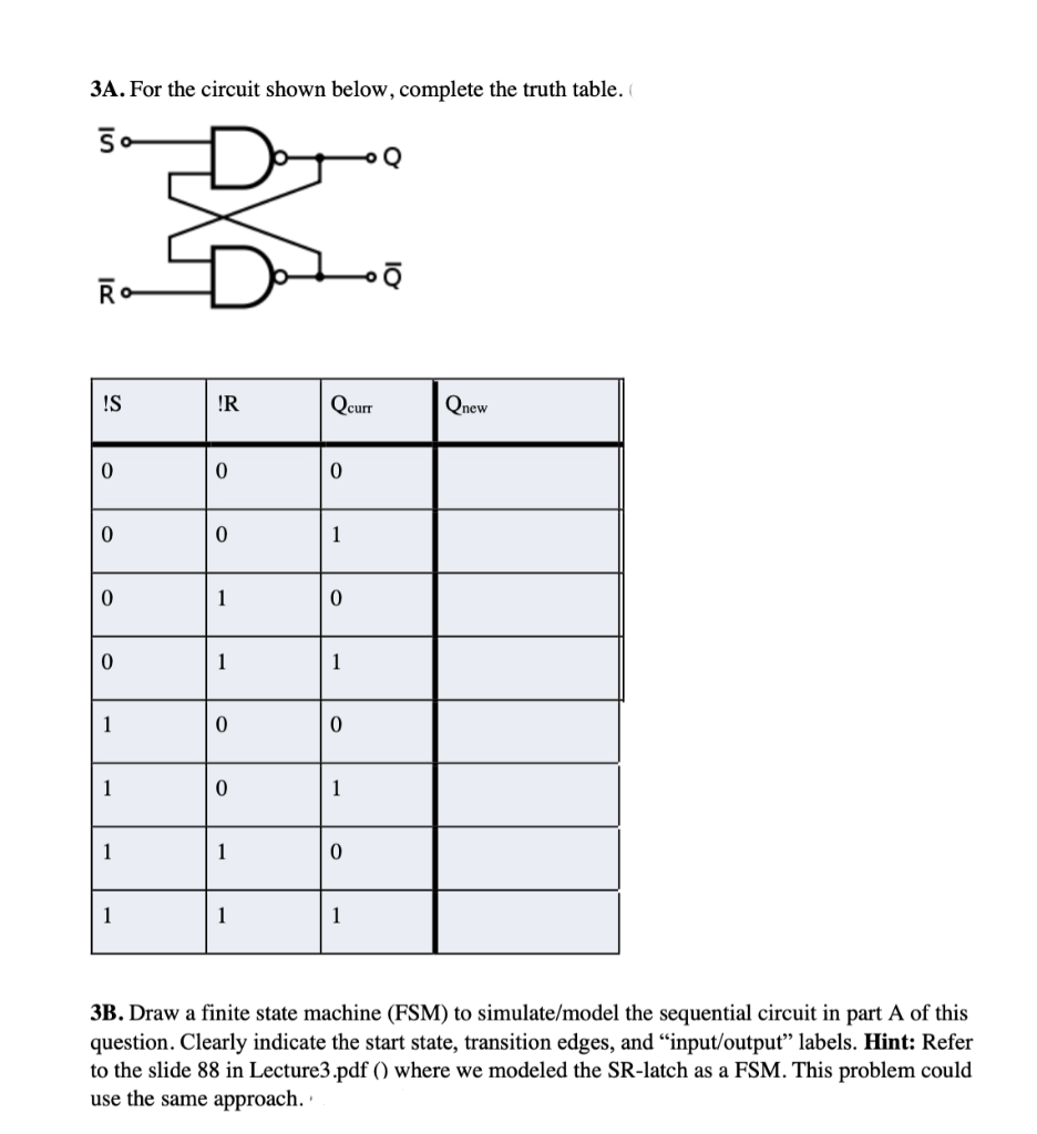
3A. For the circuit shown below, complete the truth table. 5 RO !S !R Qcurr Qnew 0 0 0 0 0 1 0 1 0 0 1 1 1 0 0 1 0 1 1 1 0 1 1 1 3B. Draw a finite state machine (FSM) to simulate/model the sequential circuit in part A of this question. Clearly indicate the start state, transition edges, and input/output labels. Hint: Refer to the slide 88 in Lecture3.pdf () where we modeled the SR-latch as a FSM. This problem could use the same approach
Step by Step Solution
There are 3 Steps involved in it
1 Expert Approved Answer
Step: 1 Unlock

Question Has Been Solved by an Expert!
Get step-by-step solutions from verified subject matter experts
Step: 2 Unlock
Step: 3 Unlock