

Question: 3c attached only for reference. The main question to be answered is the a) The following simple block diagram illustrates how one may implement an

3c attached only for reference. The main question to be answered is the a)
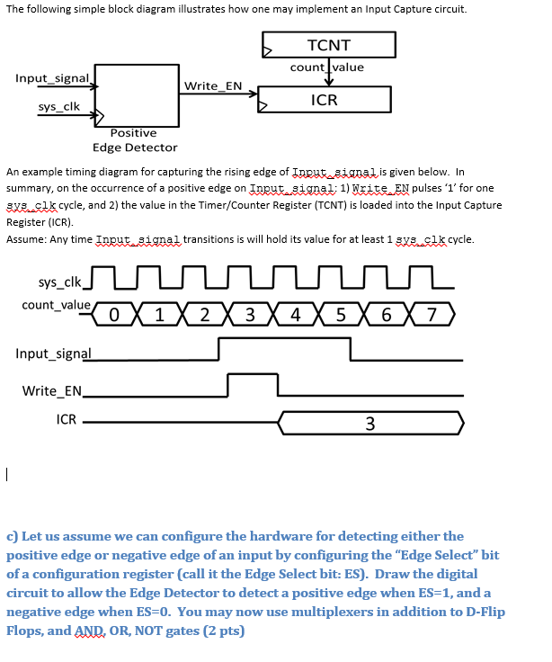
The following simple block diagram illustrates how one may implement an Input Capture circuit. An example timing diagram for capturing the rising edge of is Input_signal given below. In summary, on the occurrence of a positive edge of Input_signal: 1) Write EN pulses '1' for one sys_clk cycle, and 2) the value in the Timer/Counter Register (TCNT) is loaded into the Input Capture Register (ICR). Assume Any time Input_signal transitions is will hold its value for at least 1 sys_clk cycle. c) Let us assume we can configure the hardware for detecting either the positive edge or negative edge of an input by configuring the "Edge Select" bit of a configuration register (call it the Edge Select bit: ES). Draw the digital circuit to allow the Edge Detector to detect a positive edge when ES=1, and a negative edge when ES=0. You may now use multiplexers in addition to D-Flip negative e Flops, and AND, OR, NOT gates a) Assume the TM4C123 does not have Input Capture hardware or Interrupts. Write a C program to save TIMER's count value (i.e. TCNT1) when a positive edge event occurs on PortD, pin4. int main (void) {unsigned int rising_edge_time;//YOURCODE HERE
Step by Step Solution
There are 3 Steps involved in it

Get step-by-step solutions from verified subject matter experts