

Question: 4 pts Create a circuit that implements the state diagram below. The circuit should have a single input responsible for the state transitions described by
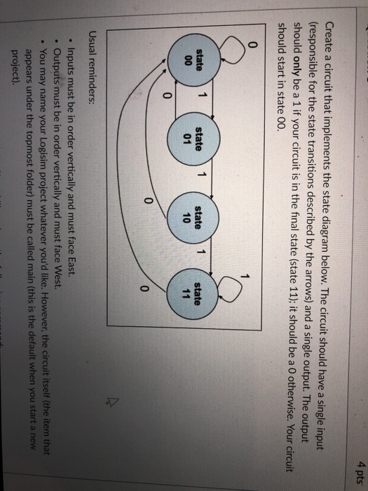
4 pts Create a circuit that implements the state diagram below. The circuit should have a single input responsible for the state transitions described by the arrows) and a single output. The output should only be a 1 if your circuit is in the final state (state 11); it should be a 0 otherwise. Your circuit should start in state 00. 0 state 1 state 1 state 1 state 01 10 0 0 Usual reminders: . Inputs must be in order vertically and must face East. Outputs must be in order vertically and must face West. . You may name your Logisim project whatever you'd like. However, the circuit itself (the item that appears under the topmost folder) must be called main (this is the default when you start a new project)
Step by Step Solution
There are 3 Steps involved in it
To implement this state machine in a circuit we need to design a sequential circuit using D flipflop... View full answer

Get step-by-step solutions from verified subject matter experts