

Question: 4) Using the data sheet posted on the course website, consider two dc machines, one rated at 5 hp, 1150 rpm and the second
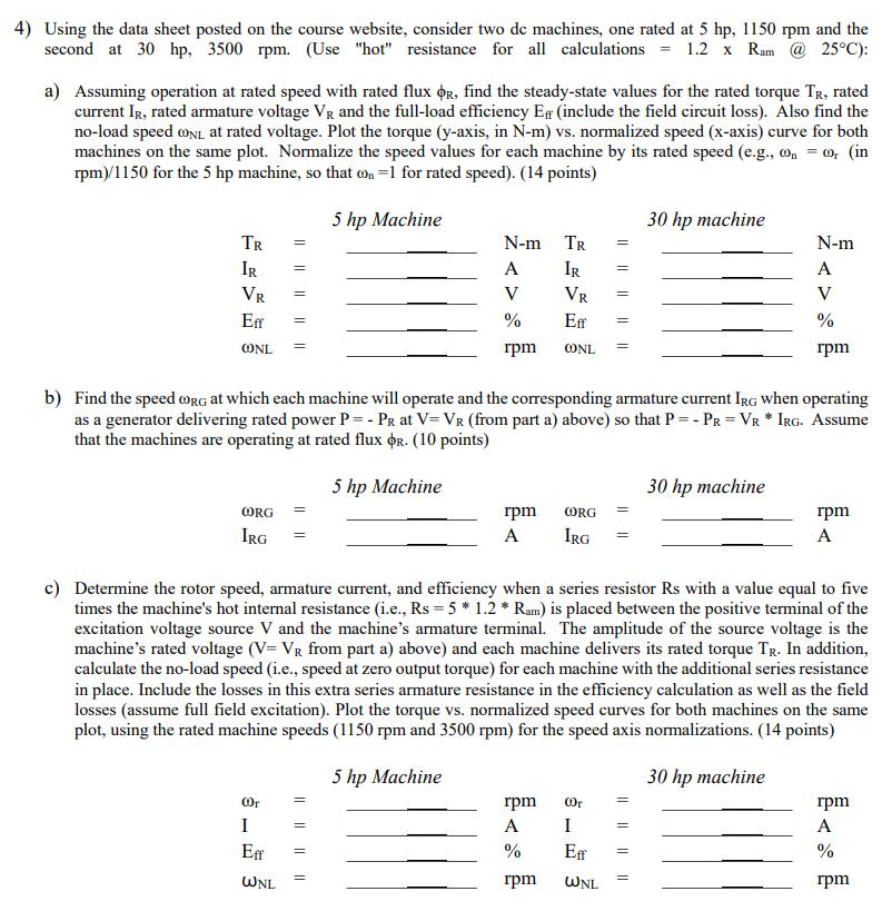
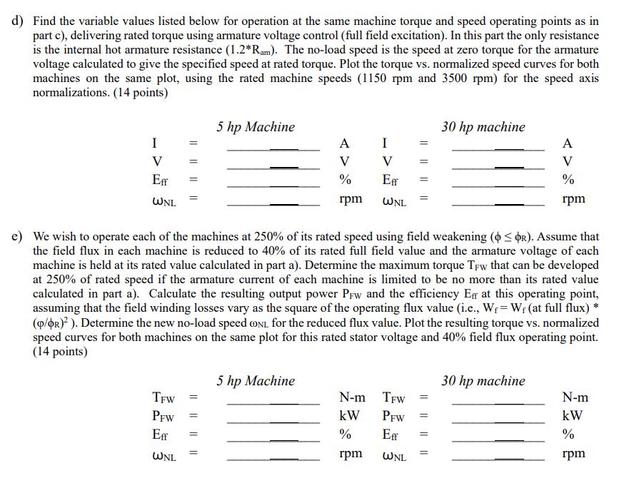
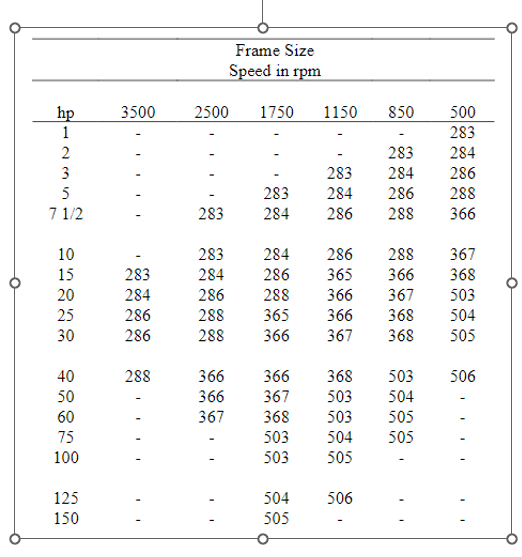
4) Using the data sheet posted on the course website, consider two dc machines, one rated at 5 hp, 1150 rpm and the second at 30 hp, 3500 rpm. (Use "hot" resistance for all calculations = 1.2 x Ram @ 25C): a) Assuming operation at rated speed with rated flux R, find the steady-state values for the rated torque TR, rated current IR, rated armature voltage VR and the full-load efficiency E# (include the field circuit loss). Also find the no-load speed CONL at rated voltage. Plot the torque (y-axis, in N-m) vs. normalized speed (x-axis) curve for both machines on the same plot. Normalize the speed values for each machine by its rated speed (e.g., con = 00, (in rpm)/1150 for the 5 hp machine, so that on=1 for rated speed). (14 points) 5 hp Machine TR IR VR Eff CONL CORG IRG 00r = I Eff WNL Nam A V % rpm b) Find the speed @ORG at which each machine will operate and the corresponding armature current IRG when operating as a generator delivering rated power P = - PR at V=VR (from part a) above) so that P = - PR = VR IRG. Assume that the machines are operating at rated flux R. (10 points) 5 hp Machine = rpm A Tr IR VR Eff CONL rpm A % rpm = = CORG = IRG c) Determine the rotor speed, armature current, and efficiency when a series resistor Rs with a value equal to five times the machine's hot internal resistance (i.e., Rs = 5 * 1.2 * Ram) is placed between the positive terminal of the excitation voltage source V and the machine's armature terminal. The amplitude of the source voltage is the machine's rated voltage (V= VR from part a) above) and each machine delivers its rated torque TR. In addition, calculate the no-load speed (i.e., speed at zero output torque) for each machine with the additional series resistance in place. Include the losses in this extra series armature resistance in the efficiency calculation as well as the field losses (assume full field excitation). Plot the torque vs. normalized speed curves for both machines on the same plot, using the rated machine speeds (1150 rpm and 3500 rpm) for the speed axis normalizations. (14 points) 5 hp Machine 00r I Eff WNL || 30 hp machine = = 30 hp machine N-m A V % rpm 30 hp machine rpm A rpm A % rpm d) Find the variable values listed below for operation at the same machine torque and speed operating points as in part c), delivering rated torque using armature voltage control (full field excitation). In this part the only resistance is the internal hot armature resistance (1.2*Ram). The no-load speed is the speed at zero torque for the armature voltage calculated to give the specified speed at rated torque. Plot the torque vs. normalized speed curves for both machines on the same plot, using the rated machine speeds (1150 rpm and 3500 rpm) for the speed axis normalizations. (14 points) I V Eff WNL TFW PFW Eff WNL 5 hp Machine = A V % rpm 5 hp Machine e) We wish to operate each of the machines at 250% of its rated speed using field weakening (OR). Assume that the field flux in each machine is reduced to 40% of its rated full field value and the armature voltage of each machine is held at its rated value calculated in part a). Determine the maximum torque TFw that can be developed at 250% of rated speed if the armature current of each machine is limited to be no more than its rated value calculated in part a). Calculate the resulting output power PFw and the efficiency E at this operating point, assuming that the field winding losses vary as the square of the operating flux value (i.e., W= W (at full flux) * (p/R)). Determine the new no-load speed CONL for the reduced flux value. Plot the resulting torque vs. normalized speed curves for both machines on the same plot for this rated stator voltage and 40% field flux operating point. (14 points) I V Eff WNL N-m kW % rpm TFW PFW = Eff WNL || 30 hp machine || A 30 hp machine % rpm N-m kW % rpm hp 3500 12310 2 5 71/2 10 15 20 25 30 40 50 60 75 100 125 150 283 284 286 286 288 2500 1750 283 Frame Size Speed in rpm 850 283 283 284 283 284 286 284 286 288 366 366 367 283 284 286 288 288 365 288 366 1150 284 286 288 367 286 365 366 368 366 367 503 366 368 504 367 368 505 366 368 503 367 503 504 368 503 505 503 504 505 503 505 504 505 500 283 284 286 288 366 506 506
Step by Step Solution
There are 3 Steps involved in it

Get step-by-step solutions from verified subject matter experts