

Question: 4.2.2 DFlip-Flop with Synchronous Reset and Load: Draw a schematic to show how you would add combinational logic along with two new inputs (RST, LOAD)
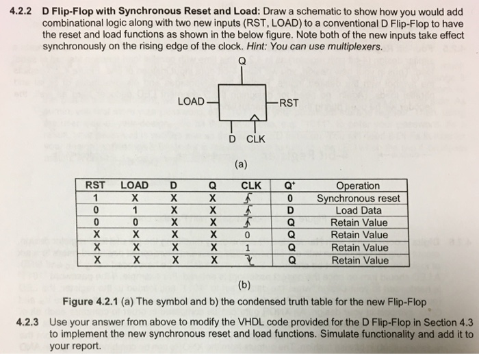
4.2.2 DFlip-Flop with Synchronous Reset and Load: Draw a schematic to show how you would add combinational logic along with two new inputs (RST, LOAD) to a conventional D Flip-Flop to have the reset and load functions as shown in the below figure. Note both of the new inputs take effect synchronously on the rising edge of the clock. Hint: You can use multiplexers. LOAD -RST D CLK CLK?Q. 0 RST LOAD D Q Operation Synchronous reset Load Data Retain Value Retain Value Retain Value Retain Value 0 Figure 4.2.1 (a) The symbol and b) the condensed truth table for the new Flip-Flop Use your answer from above to modify the VHDL code provided for the D Flip-Flop in Section 4.3 to implement the new synchronous reset and load functions. Simulate functionality and add it to your report. 4.2.3
Step by Step Solution
There are 3 Steps involved in it

Get step-by-step solutions from verified subject matter experts