

Question: 4.4 PROCEDURE 1. Use two NOR gates to construct basic SR latch circuit shown in Figure 1. Connect R and S inputs to switches A
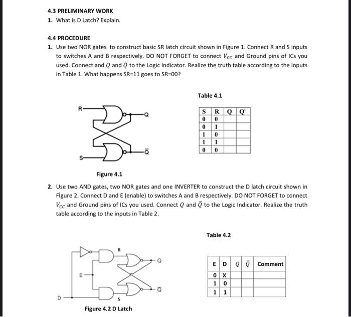
4.4 PROCEDURE 1. Use two NOR gates to construct basic SR latch circuit shown in Figure 1. Connect R and S inputs to switches A and B respectively. DO NOT FORGET to connect VCC and Ground pins of ICs you used. Connect and Q and Q to the Logic Indicator. Realize the truth table according to the inputs in Table 1. What happens SR=11 goes to SR=00 ? Table 4.1 Figure 4.1 2. Use two AND gates, two NOR gates and one INVERTER to construct the D latch circuit shown in Figure 2. Connect D and E (enable) to switches A and B respectively. DO NOT FORGET to connect VcC and Ground pins of ICs you used. Connect Q and Q to the Logic Indicator. Realize the truth table according to the inputs in Table 2. Table 4.2
Step by Step Solution
There are 3 Steps involved in it

Get step-by-step solutions from verified subject matter experts