

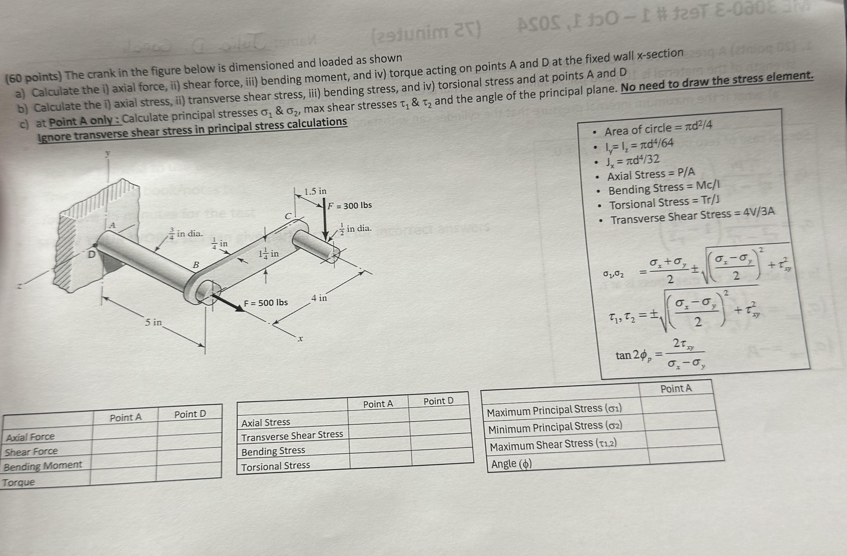
Question: ( 6 0 points ) The crank in the figure below is dimensioned and loaded as shown a ) Calculate the i ) axial force,
points The crank in the figure below is dimensioned and loaded as shown
a Calculate the i axial force, ii shear force, iii bending moment, and iv torque acting on points A and at the fixed wall section
b Calculate the i axial stress, ii transverse shear stress, iii bending stress, and iv torsional stress and at points A and
c at Point A only: Calculate principal stresses & max shear stresses & and the angle of the principal plane. No need to draw the stress element.
Ignore transverse shear stress in principal stress calculations
Area of circle
Axial Stress PA
Bending Stress
Torsional Stress Tr
Transverse Shear Stress
Step by Step Solution
There are 3 Steps involved in it
1 Expert Approved Answer
Step: 1 Unlock

Question Has Been Solved by an Expert!
Get step-by-step solutions from verified subject matter experts
Step: 2 Unlock
Step: 3 Unlock