

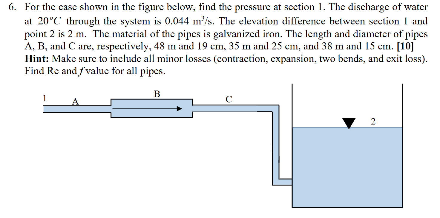
Question: 6 . For the case shown in the figure below, find the pressure at section 1 . The discharge of water at ( 2
For the case shown in the figure below, find the pressure at section The discharge of water at circmathrmC through the system is mathrm~mmathrms The elevation difference between section and point is m The material of the pipes is galvanized iron. The length and diameter of pipes mathrmAmathrmB and C are, respectively, m and mathrm~cmmathrm~m and cm and m and cm Hint: Make sure to include all minor losses contraction expansion, two bends, and exit loss Find operatornameRe and f value for all pipes.
Step by Step Solution
There are 3 Steps involved in it
1 Expert Approved Answer
Step: 1 Unlock

Question Has Been Solved by an Expert!
Get step-by-step solutions from verified subject matter experts
Step: 2 Unlock
Step: 3 Unlock