

Question: ( a ) Design and implement a memory control logic circuit using the minimum number of suitable size decoder ( s ) and logic gates.
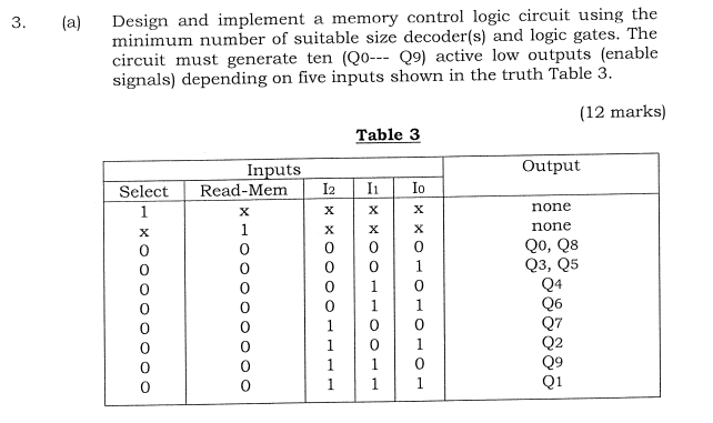
a Design and implement a memory control logic circuit using the minimum number of suitable size decoders and logic gates. The circuit must generate ten Q Q active low outputs enable signals depending on five inputs shown in the truth Table
marks
Table
tableInputsOutputSelectReadMem,IIIxxxxnonexxxxnoneQ QQ QQQQQQQ
Step by Step Solution
There are 3 Steps involved in it
1 Expert Approved Answer
Step: 1 Unlock

Question Has Been Solved by an Expert!
Get step-by-step solutions from verified subject matter experts
Step: 2 Unlock
Step: 3 Unlock