

Question: Design a majority function logic circuit using 3-to-8 Decoder In this lab, you will be designing a majority function logic circuit with three inputs (X,Y,Z)
Design a majority function logic circuit using 3-to-8 Decoder
In this lab, you will be designing a majority function logic circuit with three inputs (X,Y,Z) whose output (F) is 1 only if a majority of the inputs are 1. Implement the logic circuit using a 3-to-8 Decoder (74LS138) and any other external logic gates as necessary.
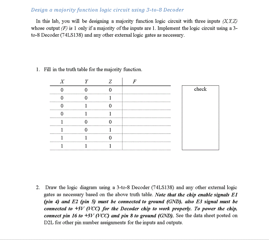
Design a majority function logic circuit using 3-to-8 Decoder In this lab, you will be designing a majority function logic circuit with three inputs YZ) whose output (F) is 1 only if a majority of the inputs are l. Implement the logic circuit using a 3- to-8 Decoder 74LS138 and any other external logic gates as necessary. 1. Fill in the truth table for the majority function. check 2. Draw the logic diagram using a 3-to-8 Decoder 4LS138) and any other external logic gates as necessary based on the above truth table. Note that the chip enable signals E1 (pin 4) and E2 (pin 5) must be connected to ground (GND), also E3 signal must be connected to +5V (VCC) for the Decoder chip to work properly. To power the chip, connect pin 16 to +5V (VCO and pin 8 to ground (GND). See the data sheet posted on D2L for other pin number assignments for the inputs and outputs
Step by Step Solution
There are 3 Steps involved in it

Get step-by-step solutions from verified subject matter experts