

Question: a ) Draw the Ladder Logic Diagram for the process below: There are two push button switches at the beginning of the belt: S 1
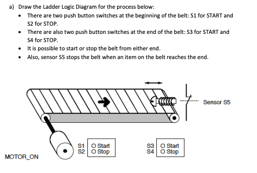
a Draw the Ladder Logic Diagram for the process below:
There are two push button switches at the beginning of the belt: S for START and
S for STOP.
There are also two push button switches at the end of the belt: S for START and
S for STOP.
It is possible to start or stop the belt from either end.
Also, sensor stops the belt when an item on the belt reaches the end.
Step by Step Solution
There are 3 Steps involved in it
1 Expert Approved Answer
Step: 1 Unlock

Question Has Been Solved by an Expert!
Get step-by-step solutions from verified subject matter experts
Step: 2 Unlock
Step: 3 Unlock