

Question: A half-wave rectifier with a capacitor filter as in Fig. 3-11a has a 220 V rms, 60 Hz ac source, R = 80 ,
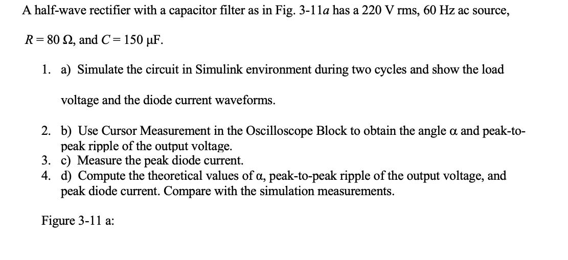
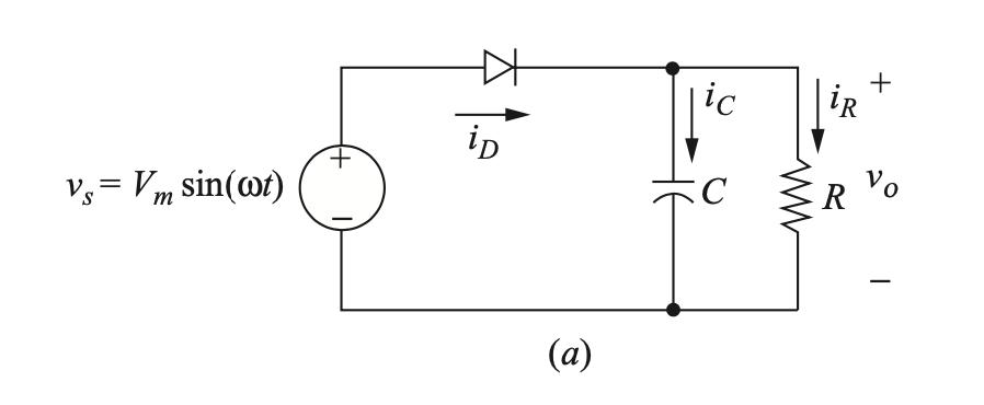
A half-wave rectifier with a capacitor filter as in Fig. 3-11a has a 220 V rms, 60 Hz ac source, R = 80 , and C = 150 F. 1. a) Simulate the circuit in Simulink environment during two cycles and show the load voltage and the diode current waveforms. 2. b) Use Cursor Measurement in the Oscilloscope Block to obtain the angle a and peak-to- peak ripple of the output voltage. 3. c) Measure the peak diode current. 4. d) Compute the theoretical values of a, peak-to-peak ripple of the output voltage, and peak diode current. Compare with the simulation measurements. Figure 3-11 a: Vs = Vm sin(wt) S + iD (a) ic KC + iR R Vo
Step by Step Solution
3.58 Rating (172 Votes )
There are 3 Steps involved in it

Get step-by-step solutions from verified subject matter experts