

Question: a). If a circuit implemented with the code given above is exited with the following sequence of inputs: a regular clock signal for a total
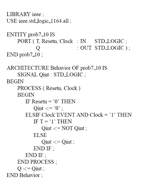
a). If a circuit implemented with the code given above is exited with the following sequence of inputs: a regular clock signal for a total of four clock periods. The Resetn is set to0 before enabling the clock and changed to 1 at the beginning of clock sequence but before the first clock change from low to high and will remain high for the duration of the test. The input T is set to 0 for the first clock and changed to 1 for the next three clock cycles.. What would be the values of the output Q for the four counts? Assume that the initially Q=0 and the change of T from 0 to 1 is carried out before the second clock pulse.
| Q=1 1 0 1 |
| Q = 0 1 0 1 |
| Q= 0 0 1 1 |
| Q = 1 0 1 0 |
| None of the above |
b).
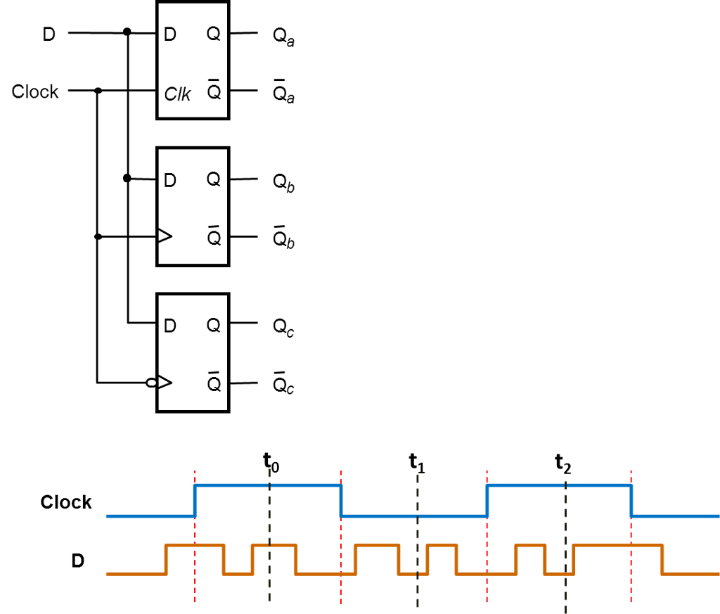
The circuit shows three types of storage elements that are driven by the same data and clock inputs what are the values of Qa, Qb and Qc for times t0,t1,t2 respectivelly?
Assume Q=0 initially.
|
| Qa = 1,0,0 Qb = 1,1,0 Qc = 0,0,0 |
|
| Qa = 1,0,0 Qb = 0,1,0 Qc = 1,0,1
|
|
| Qa = 1,0,0 Qb = 1,0,0 Qc = 0,0,1
|
|
| Qa = 1,0,0 Qb = 0,1,1 Qc = 0,0,1
|
|
| None of the above |
c).
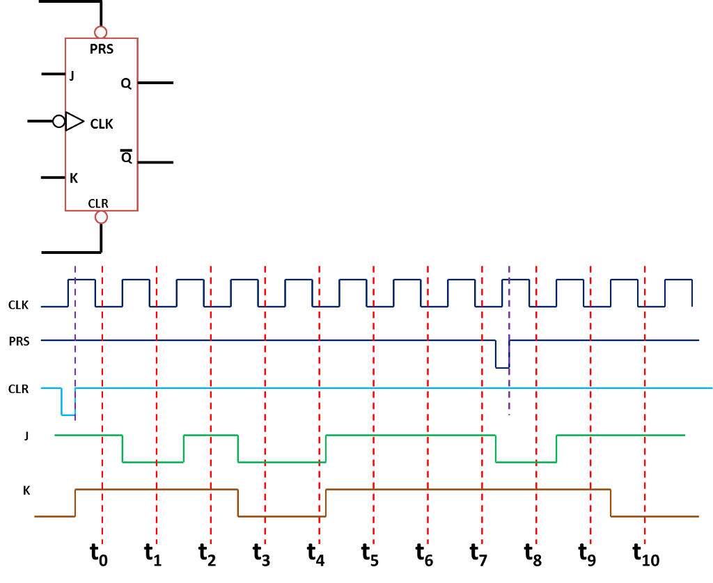
For the given JK flip-flop and its respective waveform, what are the values of Q for times t0, t2, t4, t7 and t10?
| 0 0 1 0 1 |
| 1 0 1 1 1 |
| 1 1 1 0 1 |
| None of the above |
LIBRARY ieee; USE ieee.stdlogic 1164.all; ENTITY prob7-10 IS PORT (T, Resetn, Clock IN STD_LOGIC : OUT STD LOGIC); END prob7.10; ARCHITECTURE Behavior OF prob7_10 IS BEGIN SIGNAL Qint: STD_LOGIC; PROCESS (Resetn, Clock) BEGIN IF Resetn0 THEN Qnt
Step by Step Solution
There are 3 Steps involved in it

Get step-by-step solutions from verified subject matter experts