

Question: A P+I controller is to be designed to control the voltage level in the electrical system of Figure 3. The step-response overshoot is to
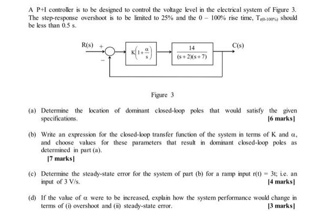
A P+I controller is to be designed to control the voltage level in the electrical system of Figure 3. The step-response overshoot is to be limited to 25% and the 0-100% rise time, Tr(0-100%) should be less than 0.5 s. R(s) + 14 (s+2)(s+7) C(s) Figure 3 (a) Determine the location of dominant closed-loop poles that would satisfy the given specifications. [6 marks] (b) Write an expression for the closed-loop transfer function of the system in terms of K and a. and choose values for these parameters that result in dominant closed-loop poles as determined in part (a). [7 marks] (e) Determine the steady-state error for the system of part (b) for a ramp input r(t) = 3t; i.e. an input of 3 V/s. [4 marks] (d) If the value of a were to be increased, explain how the system performance would change in terms of (i) overshoot and (ii) steady-state error. [3 marks]
Step by Step Solution
There are 3 Steps involved in it
a To satisfy a 25 overshoot criterion the dominant closedloop poles should be located at 38 j3... View full answer

Get step-by-step solutions from verified subject matter experts