

Question: A programmable logic controller (PLC) has to be used to control this filling process. i) Identify all the system I/O, less the connection to the
A programmable logic controller (PLC) has to be used to control this filling process. i) Identify all the system I/O, less the connection to the display, and create a PLC controller schematic using the given worksheet 3A and 3B. ii) The gate valve pneumatic schematic Figure 3b, shows a double acting cylinder briefly explain why would a single acting cylinder not be suitable for this application? iii) Sketch the emergency stop logic using the Ladder Diagram programming language. iv) Using the Ladder Diagram programming language sketch how the number of fills could be counted assuming the display unit is driven by a 16 bit integer value from the PLC addressed as QW30. v) Sketch a sequential function chart (SFC) to implement the filling process. vi) The control system has to have a Human Machine Interface (HMI) device added to the operator station. One of the tasks of the HMI are to allow the reseting of the Number of Fills counter. Briefly explain the steps required to achieve this sketching any modifications to the PLC Ladder Diagram program required. vii) Discuss how failures in the filling machine could be detected identifying any additional sensors that would be required for this to be possible.
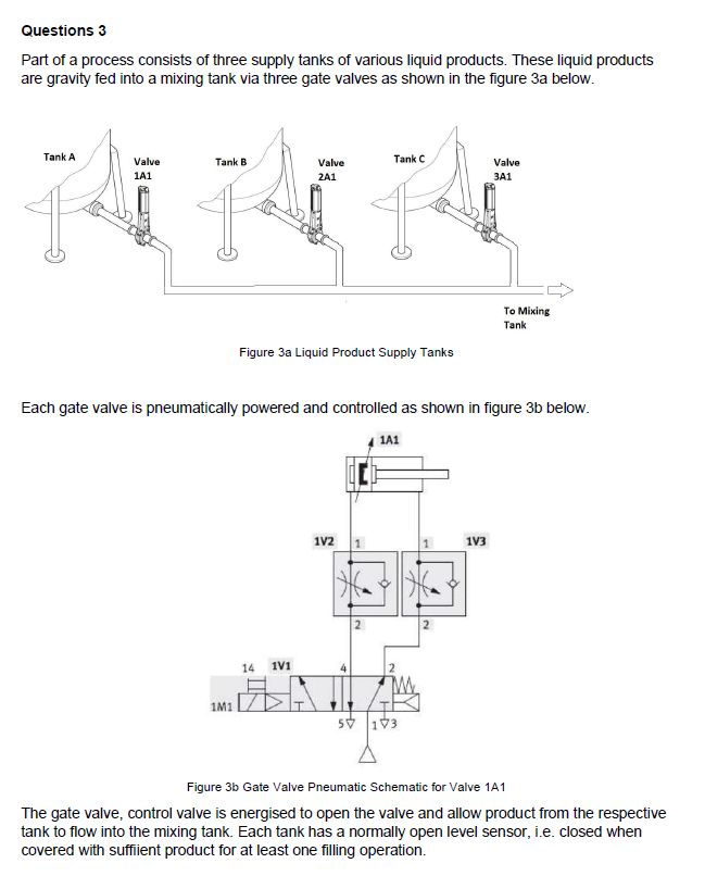
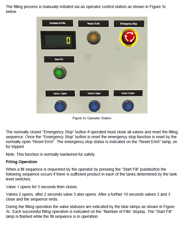
Part of a process consists of three supply tanks of various liquid products. These liquid products are gravity fed into a mixing tank via three gate valves as shown in the figure 3 a below. Figure 3a Liquid Product Supply Tanks Each gate valve is pneumatically powered and controlled as shown in figure 3b below. Figure 3b Gate Valve Pneumatic Schematic for Valve 1A1 The gate valve, control valve is energised to open the valve and allow product from the respective tank to flow into the mixing tank. Each tank has a normally open level sensor, i.e. closed when covered with suffiient product for at least one filling operation. The filling process is manually initiated via an operator control station as shown in Figure 3c below. Figure 3c Operator Station The normally closed "Emergency Stop" button if operated must close all valves and reset the filling sequence. Once the "Emergency Stop" button is reset the emergency stop function is reset by the normally open "Reset EmS". The emergency stop status is indicated on the "Reset EmS" lamp, on for tripped. Note: This function is normally hardwired for safety. Filling Operation When a fill sequence is requested by the operator by pressing the "Start Fill" pushbutton the following sequence occurs if there is sufficient product in each of the tanks determined by the tank level switches. Valve 1 opens for 5 seconds then closes. Valves 2 opens, after 2 seconds valve 3 also opens. After a further 10 seconds valves 2 and 3 close and the sequence ends. During the filling operation the valve statuses are indicated by the blue lamps as shown in Figure 3c. Each successful filling operation is indicated on the "Number of Fills" display. The "Start Fill" lamp is flashed while the fill sequence is in operation
Step by Step Solution
There are 3 Steps involved in it

Get step-by-step solutions from verified subject matter experts