

Question: A single phase line is modeled as an inductive reactance as shown in Figure 1 1 . 7 . In this case, 1 0 .
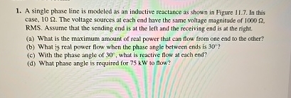
A single phase line is modeled as an inductive reactance as shown in Figure In this case, The voltage sources at ench end have the same voltage magnitude of RMS Assume that the sending end is at the left and the receiving end is at the right.
a What is the maximum amount of real power that can flow from one end to the other?
b What is real power flow when the phase angle between ends is
c With the phase angle of what is reactive flow at each end?
d What phase angle is required for kW to flow?
Step by Step Solution
There are 3 Steps involved in it
1 Expert Approved Answer
Step: 1 Unlock

Question Has Been Solved by an Expert!
Get step-by-step solutions from verified subject matter experts
Step: 2 Unlock
Step: 3 Unlock