

Question: A two-bar planar truss structure has the geometry as shown in Figure Q2. A concentrated force P=200 kN is applied to the truss at
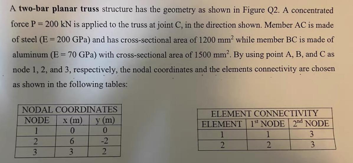
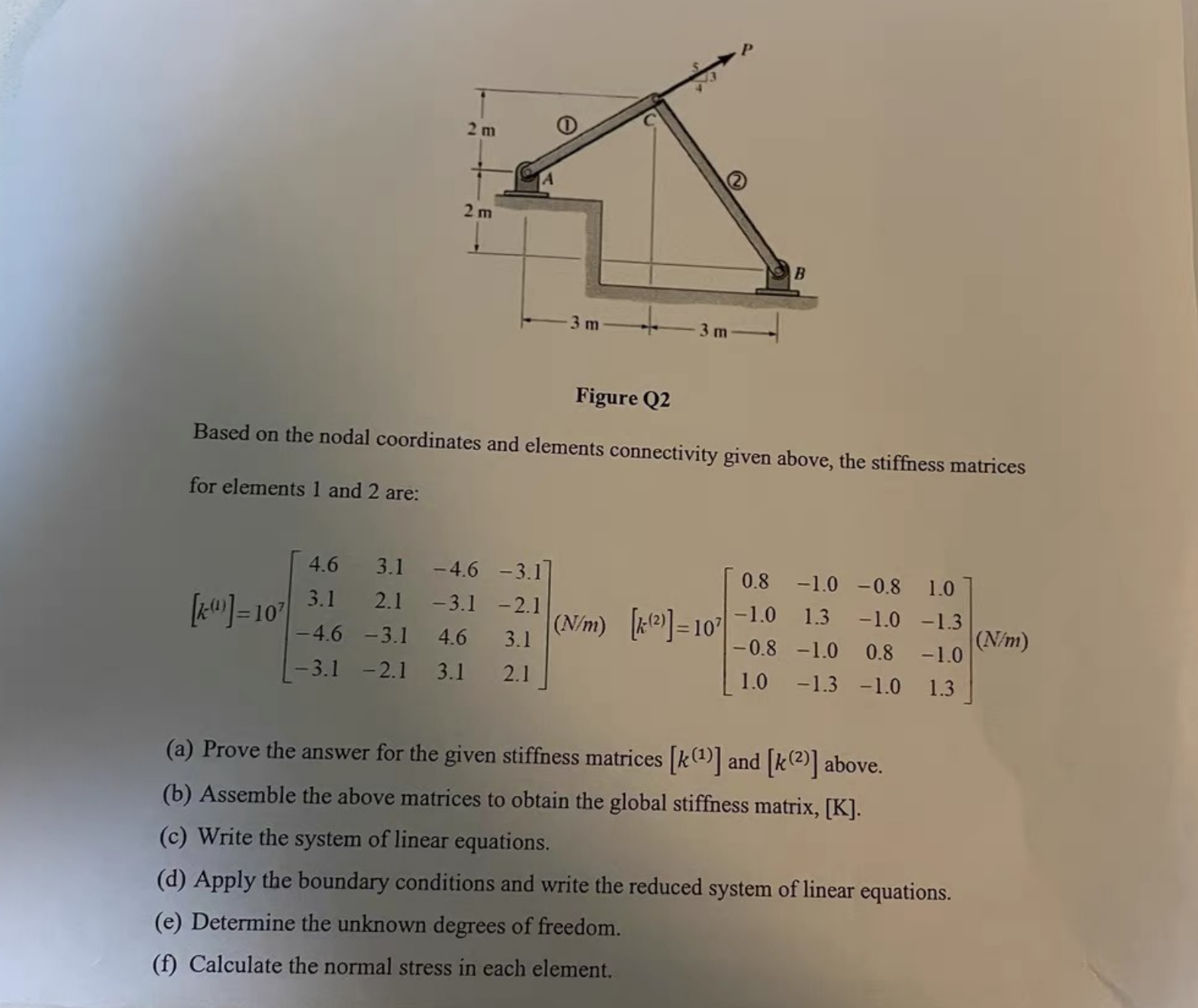
A two-bar planar truss structure has the geometry as shown in Figure Q2. A concentrated force P=200 kN is applied to the truss at joint C, in the direction shown. Member AC is made of steel (E200 GPa) and has cross-sectional area of 1200 mm while member BC is made of aluminum (E = 70 GPa) with cross-sectional area of 1500 mm. By using point A, B, and C as node 1, 2, and 3, respectively, the nodal coordinates and the elements connectivity are chosen as shown in the following tables: NODAL COORDINATES NODE 1 2 3 x (m) 0 6 3 y (m) 0 -2 2 ELEMENT CONNECTIVITY ELEMENT 1st NODE 2nd NODE 3 2 2 3 for elements 1 and 2 are: 2 m [*]=10 2m 3 m Figure Q2 Based on the nodal coordinates and elements connectivity given above, the stiffness matrices 4.6 3.1 -4.6 -3.1] 3.1 2.1 -3.1-2.1 -4.6 -3.1 4.6 3.1 -3.1 -2.1 3.1 2.1 3 m B (N/m) [(2)]=107 0.8 -1.0 -0.8 1.0 -1.0 1.3 -1.0 -1.3 0.8 -1.0 -0.8 -1.0 1.0 -1.3 -1.0 1.3 (a) Prove the answer for the given stiffness matrices [k()] and [k()] above. (b) Assemble the above matrices to obtain the global stiffness matrix, [K]. (c) Write the system of linear equations. (d) Apply the boundary conditions and write the reduced system of linear equations. (e) Determine the unknown degrees of freedom. (f) Calculate the normal stress in each element. (N/m)
Step by Step Solution
There are 3 Steps involved in it

Get step-by-step solutions from verified subject matter experts