

Question: An electrical system is shown in the Figure 1. Assuming output as V:(t), Obtain, a) the set of differential equations governing the system b)
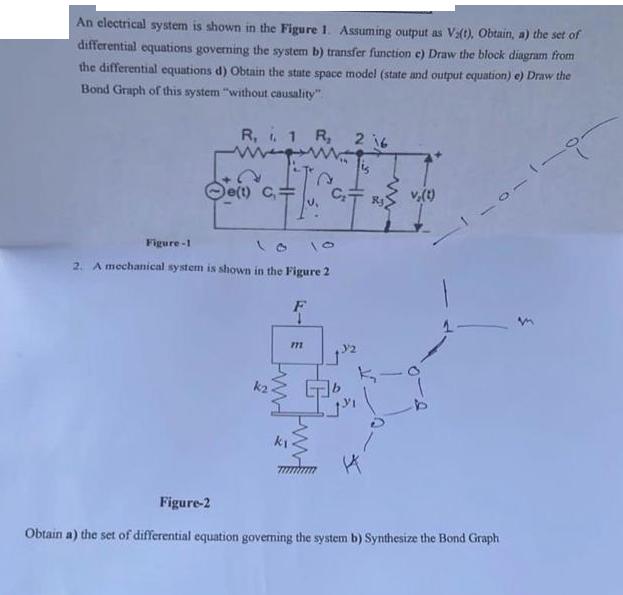
An electrical system is shown in the Figure 1. Assuming output as V:(t), Obtain, a) the set of differential equations governing the system b) transfer function e) Draw the block diagram from the differential equations d) Obtain the state space model (state and output equation) e) Draw the Bond Graph of this system "without causality" R, i. 1 R, 216 Figure-1 De(t) C 2. A mechanical system is shown in the Figure 2 Figure-2 St FM 4- F 771 k www. v(t) 10-1-9 Obtain a) the set of differential equation governing the system b) Synthesize the Bond Graph
Step by Step Solution
3.41 Rating (154 Votes )
There are 3 Steps involved in it
Steps Step 1 of 2 a Differential equations governing the system di dt Vit R it L du C it dt where Vi ... View full answer

Get step-by-step solutions from verified subject matter experts