

Question: Analog electronics - Active filter 2.2. Design a fifth order Butterworth high pass active filter for the critical frequency in 2.1. Show all relevant calculation
Analog electronics - Active filter
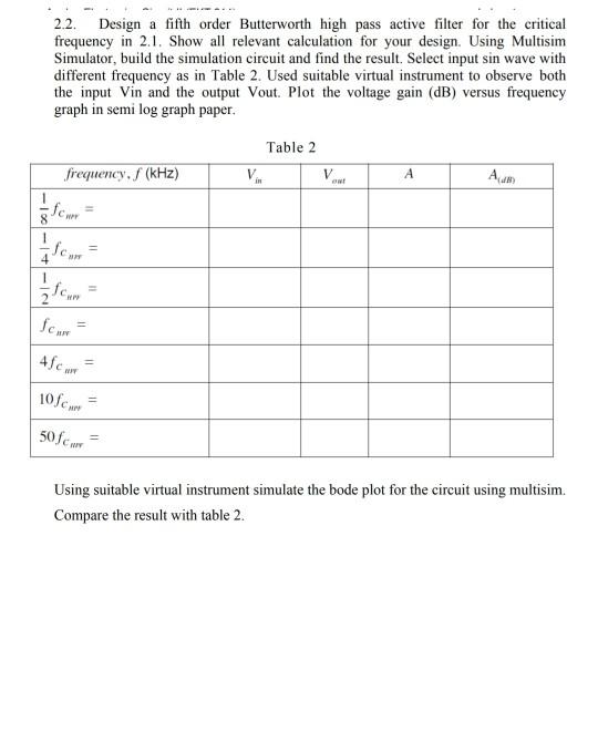
2.2. Design a fifth order Butterworth high pass active filter for the critical frequency in 2.1. Show all relevant calculation for your design. Using Multisim Simulator, build the simulation circuit and find the result. Select input sin wave with different frequency as in Table 2. Used suitable virtual instrument to observe both the input Vin and the output Vout. Plot the voltage gain (dB) versus frequency graph in semi log graph paper. Table 2 V frequency. S (kHz) w w 8 Scan 4 = HP Scan 45cm 105cm 50fc WY Using suitable virtual instrument simulate the bode plot for the circuit using multisim. Compare the result with table 2. 2.2. Design a fifth order Butterworth high pass active filter for the critical frequency in 2.1. Show all relevant calculation for your design. Using Multisim Simulator, build the simulation circuit and find the result. Select input sin wave with different frequency as in Table 2. Used suitable virtual instrument to observe both the input Vin and the output Vout. Plot the voltage gain (dB) versus frequency graph in semi log graph paper. Table 2 V frequency. S (kHz) w w 8 Scan 4 = HP Scan 45cm 105cm 50fc WY Using suitable virtual instrument simulate the bode plot for the circuit using multisim. Compare the result with table 2
Step by Step Solution
There are 3 Steps involved in it

Get step-by-step solutions from verified subject matter experts